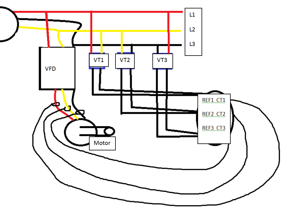
Hi all, I’m working on a project to monitor and log power consumption of a 3-phase motor and I have a few questions. The motor is controlled by a VFD and will rotate in one direction for 6 seconds then change directions for 6 seconds and repeats.
Right now I have 3 transformers to step down 230V L-L to use as my reference voltages for phases A,B,C. Phase_a is wired with L1&L2, phase_b is L2&L3, phase_c is L3&L1.
Is this correct wiring for each phase?
I am using 3 ECS1050 CTs and they are connected to the terminals of the motor. Each are hooked around one of the 3 terminal wires of my motor pointing in the same direction.
How do I properly configure the CTs? Do each get a different VRef, so phase_a, phase_b, phase_c? Should enable “Allow negative power value”? And do I enable “Double”?
To calculate total power consumption of the motor is that as simple as summing the 3 watt values I get from the CTs or do I use a different formula?
CCFirst, can you provide a line diagram of the circuit?
When you say it’s controlled by a VFD, that usually means an inverter that produces variable frequency and voltage to the motor. While it’s theoretically possible to monitor that VFD output and determine power, if it really is a VFD, it might make more sense to monitor the power into the VFD than out.
What is the input to the VFD? Is it single or three-phase, and if it’s three phase, is there a alsoa neutral wire?
The rule is that to measure power, you need one less CT than the number of conductors. So in the case of the motor, what you describe is three-wire, or delta connected. You can do that with two CTs and two VTs. There are three symmetrical ways to connect. One way is;
CT on L1 with VT on L1-L3 voltage
CT on L2 with VT on L2-L3 voltage
Adding the power of the two CTs would give total power to the motor. Reversing should be handled fine by this. You could also use derived reference to eliminate one of the VTs.
But sketch-up a line drawing showing the service circuit, VFD and motor. I think you would be best off monitoring the. VFD input.
UPDATE: on second thought, reversing may not measure correctly with derived reference.
Thank you for the speedy response! I will make the change and move the CTs to the input of the VFD. The VFD is three-phase in and out with a grounding wire connected to both the VFD and the Motor. The motor is Y connected.
So if I’m getting this right, the total power for the motor and VFD will the sum of CT1 and CT2?
And do I need to change parameters on the CTs like “Allow negative power value” of “Double”?
Again thanks for the help. Here’s my sketch of the circuit.
The motor does not appear to be Y connected. It has three wires and so is delta, as I would expect for a VFD controlled motor.
The CTs need to be on the input to the VFD. the frequency and voltage of the VFD output will vary and bear no relationship to the input frequency and voltage.
I have moved the CTs to the input of the VFD so that has been changed. I The VTs are getting about 230V AC and it gets trasformed to 10.8V AC.
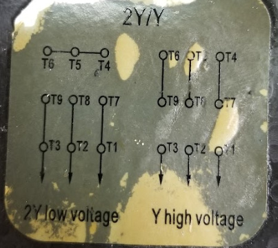
I’m not an expert on wiring motors. The way I have the motor configuration is “2Y low voltage.” The 3 phase coming from the VFD is connected to T9&T3, T8&T2, T7&T1. And a grounding wire to the case of the motor.
I’m a little skeptical that diagram is correct. It does show a delta configuration as there’s are no neutral wires, and 230V is more common phase to neutral, which would be wye. What country is this?
I don’t doubt the motor is working right. I’m just unfamiliar with what you are describing, so I can’t say how to measure the power usage.
In the US, I typically see 120V/208V or 277V/480V three-phase systems. The lower voltage in each pair is the “Wye” connected voltage between a fourth common conductor and any of the three hot conductors, and the higher is the phase-to-phase voltage between any two hot conductors. In your diagram you show the VTs phase-to-phase and say the voltage is 230V.
A VFD, as I understand them, will produce a variable frequency and voltage to control the motor speed, as the name implies - Variable Frequency Drive. That’s why I recommended connecting the VTs and CTs on the line side of the VFD and measure the power used by the VFD/motor combination. Probably more useful data anyway.
If your system truly is wired as diagrammed and described, then it would be measured with:
CT on the L1 lead to the VFD with Vref = REF3
CT on the L2 lead to the VFD with Vref = REF2
Do not check the “double” box.
Add the L1 and L2 power for total power.