I am having a problem with which phase to allocate to my air conditioner.
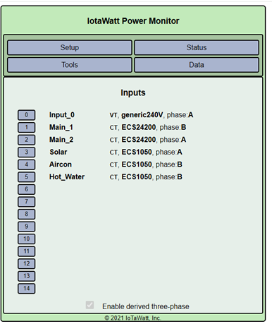
The allocation of inputs are shown below. I have nominated input 2 as A phase so that some unmonitored loads read correctly.
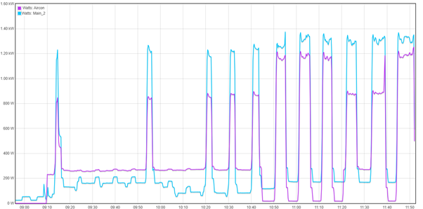
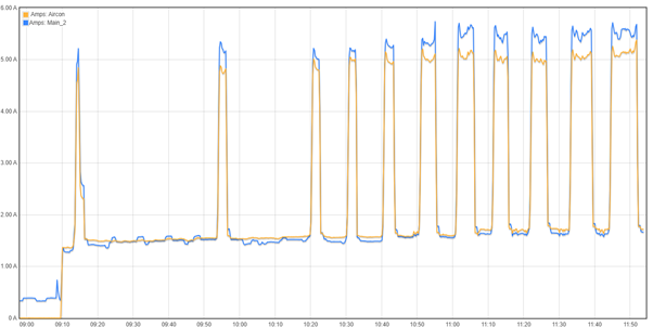
A section of the power graph and current graph are also shown below.
One problem is that the aircon is allocated to phase B but from the graphs it is connected to Main_2 which is phase A.
I changed the allocation of the aircon to see the effect on the power graph. The aircon is allocated to phase A 9:00am to10:45 and 11:22 to 11:38 and on phase B from 10:45 to11:22 and 11:38 to 11:50+.
From the current graph connection to phase A gives correct values to the low values of power but not the high values while the opposite applies to phase B The Main_2 reading are correct in both cases. Your thoughts please.
Do you have 3 phase power? If you do, where’s phase C? And if you don’t, you’re set up way wrong. You only have 2 mains listed (and your VT is labeled generic 240V) so I think you need to follow the standard “split-phase” setup:
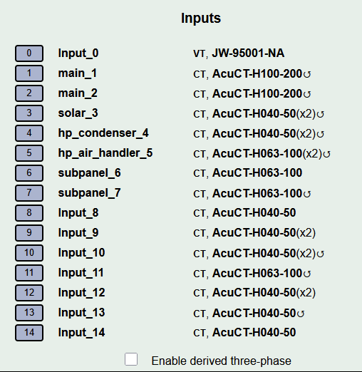
I’m in north america with standard 200A split-phase service and here’s my inputs:
I am in Australia and have two phase and neutral connected of a three phase four wire 415/240 volt system. Is there any requirement for input 1 to be on the same phase as the voltage reference?
main_1 and main_2 are connected to sub mains to a sub board and measure all of the load except hot water which is a load controlled circuit off one of the phases.
Please read and follow the directions for configuring derived three phase. Trial and error does not work very well. There are dozens of incorrect combinations and only one correct one.
Also, looking at amps will tell you nothing about voltage/phase relationships as you can see by your second graph.
No, but it gets complicated when its not. Since all of your loads are 240V single phase and you only have two of the three phases, you might consider using direct voltage reference rather than derived. To do so, you would:
Set all of the circuits to “phase A”.
Add another VT connected to the other phase.
When you configure the other VT, all of the inputs will allow you to select which voltage reference to use for that input.
Go down the list and assign the corresponding voltage reference for each circuit.