I have just completed a new install of my IoTaWatt (Thanks @overeasy!). I did have a few questions based on the initial setup and data. Just making sure that my initial thoughts and troubleshooting is correct. I do not yet have the mains installed, only two sub panels (garage and barn) and a few 240v and a couple 120v circuits.
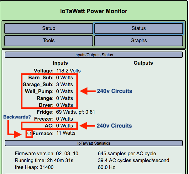
The easy question which seems easy to start with is the reverse/backwards icon, I assume this is a CT installed backwards due to the indicator. Do I simply reverse the CT and all should be good? This is a 120v circuit.
I was wondering the best way to troubleshoot the 240v circuits marked in the image above. Do I take for example the Dryer and double the volts or watts in the Output to get the actual value? I did have a look here: LINK: Home · boblemaire/IoTaWatt Wiki · GitHub where it says
“You can measure some (US) 240volt circuits with a single CT on one of the conductors, then create an output that multiplies that value by 2 to get the true watts.”
Just not sure which to double as in some cases (Range and Dryer) I’m seeing very high wattages as they are currently configured via a single CT. Can someone point me to some other details or help for a beginner to allow me to walk through various scenarios to ensure I’m monitoring the correct items?
The Garage sub panel I’m seeing activity with the Garage Doors, etc. But I see nothing from the Barn placing the 100amp CT on the red (the wires are too large for a single CT to have both enclosed. Maybe this one will require monitoring with two CTs?
If you reverse the CT, the icon will go away… or you can just leave it as is. It’s just telling you that the reported power was negative and it has been corrected.
If you run both conductors through the CT, the reported value should be correct. If you only run one conductor through, you need to double the reported value. If you have two conductors through the CT and the reported value is zero when you know there is a load, then one of the conductors is not reversed.
As above for doubling. What is high wattage for one appliance can be normal for another. Ranges and dryers use a lot. As previously discussed, those two appliances should have both conductors through the CT. In general, I would recommend running both conductors through the CT whenever possible, as it naturally reports the correct power with no need to double. There is no downside except the case where the appliance is a true 240V appliance and the power exceeds the rating of the CT.
With only one conductor monitored in the barn sub-panel, you will only see 120V loads on that side of the panel, and half of the power for any 240V loads. You can add another CT to the black conductor and add the two for the total, of you can get a larger CT and clamp it around both with one reversed.
I had mentioned possibly having those larger cables for the barn sub-panel moved to make more room to monitor the mains. At the same time, the loop up there near the top of the panel could be manipulated to put a CT around both with one reversed, or the excess could be pulled down in the box to create a similar loop beside and below the breaker and the CT could be installed there. You probably need an ECS16100 for that large barn cable.
@overeasy again thanks for the feedback. Just for clarification on US 240v circuits. If there is a black and red wire coming from the 240v breaker, I should always (not just for the sub panels) try to first do the one twisted and the other straight through. Is this the best way to start troubleshooting anything that is on both legs of the panel? AC, Dryer, Pump, etc. I should assume that like with the sub panels, I would see voltage/watts half the time and not the other half if I do not do the twist? In the case of the barn, I may want to pick up another 100A for the other leg as the wires are just too big. I will try to move that one to the other wire when I go in and reverse the ones that are currently backwards.
Thanks for the reply and directing me on the right path of better monitoring and also educating along the way.
I think I have the same info from the previous CT Install Question thread where you said
MY QUESTION: The best option in your opinion is to go with reversed leg (twist one phase) in the CT for all 240 based circuits in the panel?
YOUR REPLY: It takes away any guesswork as to whether there is a 120V component. I don’t expect users to have the fundamental understanding of how these circuits and appliances operate, and I don’t think it should be necessary. So yes, On balance I think this is the best universal recommendation.
That said, an electrician would know whether any particular circuit is true 240, and there could be circumstances where measuring just one leg could be useful. For example, if the CT available is not rated for the full current of both legs, or if the panel is wired in such a way that it would require modification to add the reversed leg.
With this information, I will make try to add the reverse twist in all my 240v circuits having a single CT installed. That is I’m sure why I only see some usage and at times negative as the other leg is providing the power.
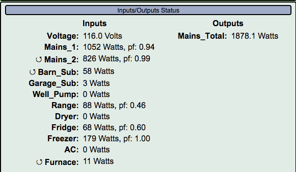
@overeasy quick question. I had some time to get the mains CTs up and running; one needs to be reversed as in the near future we will have solar and the ability to have negative values.
I did the twists on all my 240v CTs except for the Barn Sub due to the cable size. That one I will double instead.
One question, now that I did the twist move, the AC 240v is showing 0 watts as shown below when on. Does that mean it is a true 240v and I should only put the CT on a single leg? It was working like that yesterday before I put in the twist.
Doesn’t matter if it’s pure 240V or 120/240. It should work the same. Please post a picture of the CT installation in question? Also, is it securely plugged into the IoTaWatt? Make sure it clicks into the jack.
Roger. I will have a look and make sure that it did not come disconnected in the panel as some of the bigger cables make for a tight fit. Once I have them all working and in the right direction, I plan on putting cable ties around each to keep them in place. Thanks for the product and support.
I’m in the process of updating the WiKi and intend to add a page to discuss the various options and requirements for 240V circuits. Hopefully by the end of the week.
Also, the latest release has an option to specify that a circuit is a true 240V circuit.
While Overeasy makes updates to the Wiki, you can also have a look at the thread below and about 1/3 of the way down Bob provides some examples to me on 240v circuits. Some of this may be updated with the newer code release, but still good for reference and answering many questions.
Simply click on the title below and it will take you to the post.