Hi everyone,
before I start I want to mention that this post is a copy of my post in the openenergymonitor forum that can be found here. I am not a fan of cross posting but a user there mentioned I should try it in this forum as the chances are higher of getting help. If this is not OK please let me know or delete this post!
I am quite new to the topic of energy monitoring. I bought an IotaWatt and some SCT013 and SCT006. My plan is to use the SCT013 to measure the main leads coming into the distribution board and use the SCT006 for additional per-room measurements. I was now playing around with the stuff I got and was little confused about the readings I get.
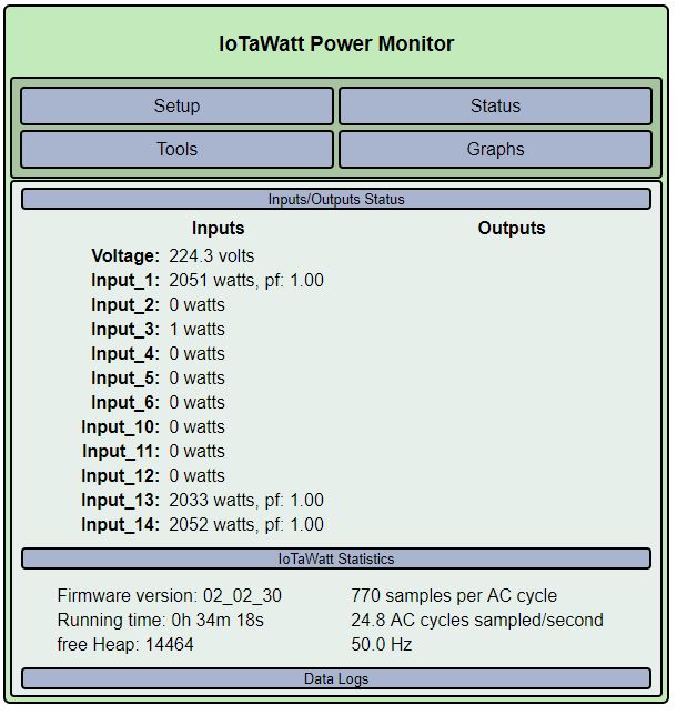
I hooked up a hot air gun into a power meter, and measured the current on the lead using one SCT013 and two SCT006. I noticed, that the power readings of the two different CTs differ significantly as you can see in the following screenshot:
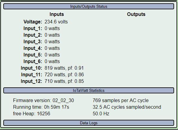
The measurement of the SCT013 seems to be spot on (less than 1% difference compared to the power meter), but the readings of both SCT006 are really bad. Additionally they differ significantly each to another. The readings you see in the screenshots where made by additionally pressing them shut, without that, the gap between them is even worse.
The power factor reported by the SCT013 is spot on to that measured by the power meter, but again the SCT006 show significant differences.
What could be the problem here? Is this the expected accuracy of the SCT006? (I hope not, I ordered a bunch of them xD…). Is there anything I can do to improve the accuracy of these CTs?
Thanks and Regards,
Jan
I agree, that doesn’t look right. There are a few things that could be causing this. First some history with the SCT006:
I have two of the original four CTs that were sent to OEM for evaluation a year or so ago. I tested them in the US 60Hz environment because that was the reason for sourcing a smaller CT - a small inexpensive CT to fit inside a crowded US main panel to measure circuits that are protected with 20A breakers. The samples that I got worked OK to 20A and fell off sharply after that. It was determined that these would do an adequate job for US installations.
Some time after OEM acquired a quantity shipment, and folks in Europe siezed on them as a bargain sensor, it was determined that the newer batch did not perform like the samples that I tested. They saturated at a lower current. It was also determined that they had lower limits in the 50Hz environment.
But none of the testing or controversy about the saturation current raised any question of accuracy below the saturation point, which in your case might be conservatively estimated at about 15amps. The status display that you posted indicates current of less than 4 amps, so saturation isn’t at play here.
I took those two initial sample SCT006’s and connected them to a load with a similar power factor:
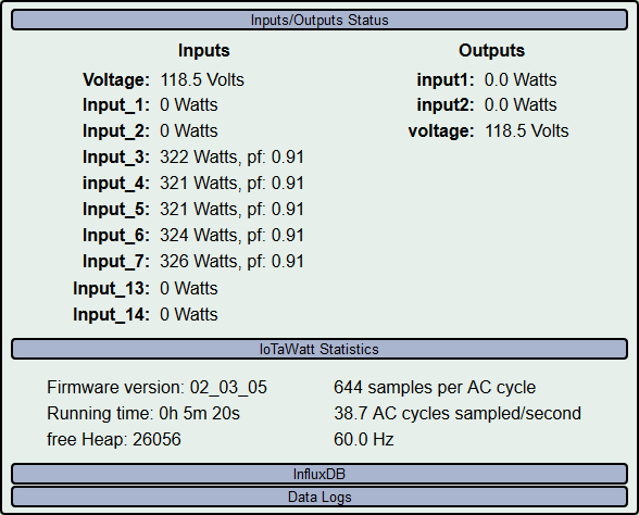
- Input_3 is an eChun ECS1050
- Input_4 is an SCT013-000
- Input_5 is an SCT013-000
- Input_6 is an SCT006
- Input_7 is an SCT006
All of them are clamped around two turns of the test current, which yields a little under 3 Amps. The SCT006’s are reading about 1% higher than the other three. I want to point out that they all show the same power factor.
In your case, not only are the SCT006’s showing 12% less real power, they are showing significantly lower power factor. So it’s not just a matter of calibration, there is something wrong.
I suspect these CTs are either not clamped securely or have defective/damaged metal cores. Inspect the mating surfaces of the metal core and insure they are smooth and clean and mate squarely when you clamp it around the wire. Try squeezing the two halfs while measuring to see if that changes the readings.
These SCT006 CTs are cheap in every sense of the word, but you should be able to get within 1%-2% of the SCT013 with them.
Thank you for your in depth reply, I will try to do some more testing in the coming days. I will let you know when I have new findings!
Hi,
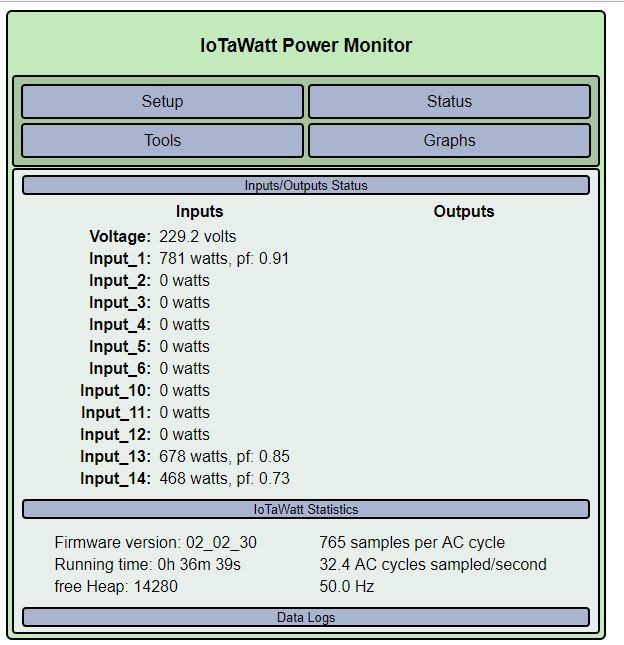
sorry it took me a few weeks longer for my testing. I took a look at the CTs again and I could find no damage or defects on the metal cores. I redid the testing, this time with a water boiler and again with the hot air gun. In the first screenshot you see the measurements with the water boiler:
As you can see the power factor now is reported as 1 by all CTs. My wall power meter reported 2035 watts. Again the CT’s are far away from being precise or consistent to each other. This time the SCT013 seems to be off by quite a bit, but I am not sure my wall meter is really that precise.
In the next screenshot you see the results with the hot air gun again:
You can see nothing has really changed to the last results I got. I also tried pushing the cores together, without any significant change (in both test cases). Again the power factors are all over the place as wall as the power readings itself.
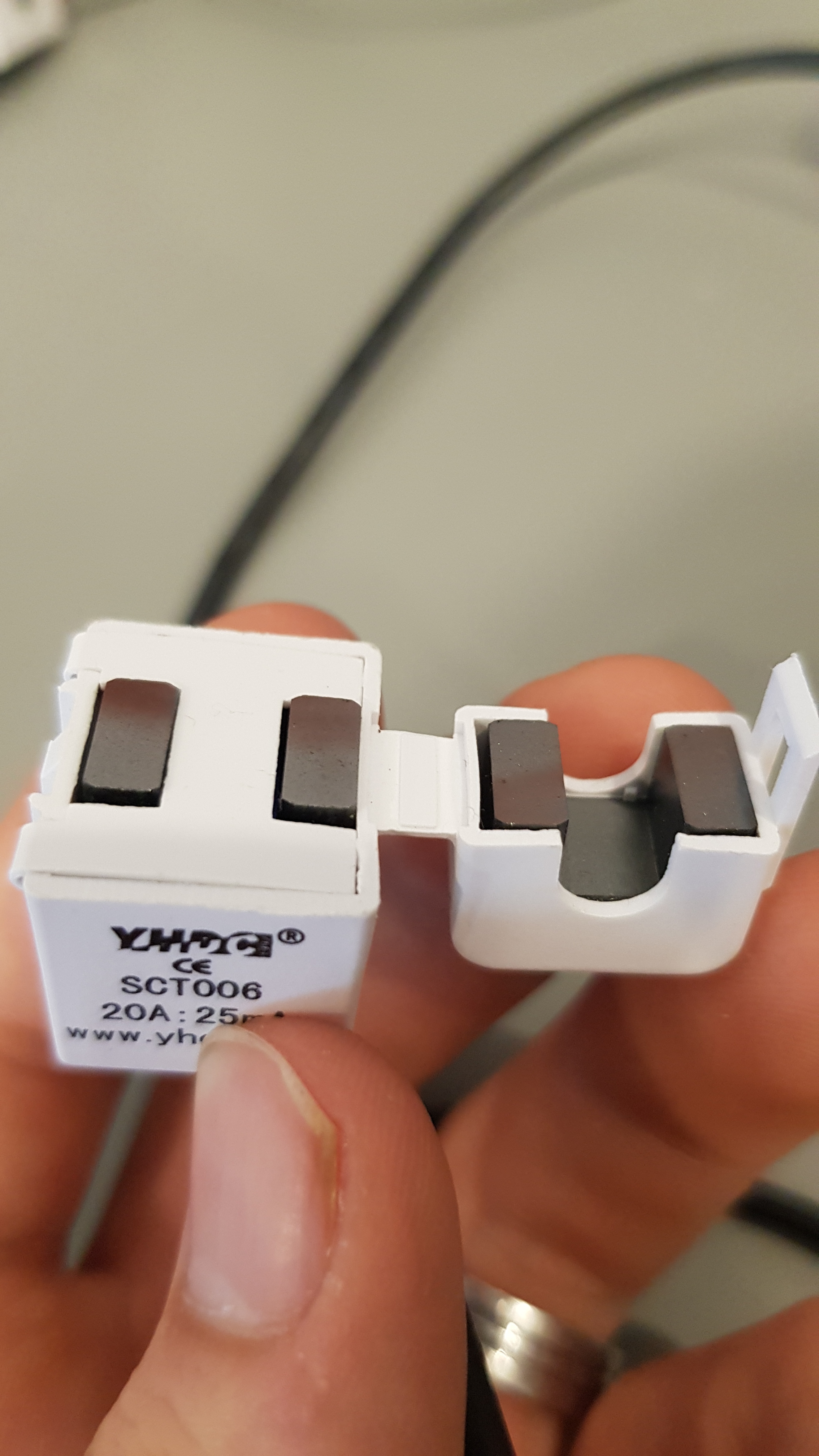
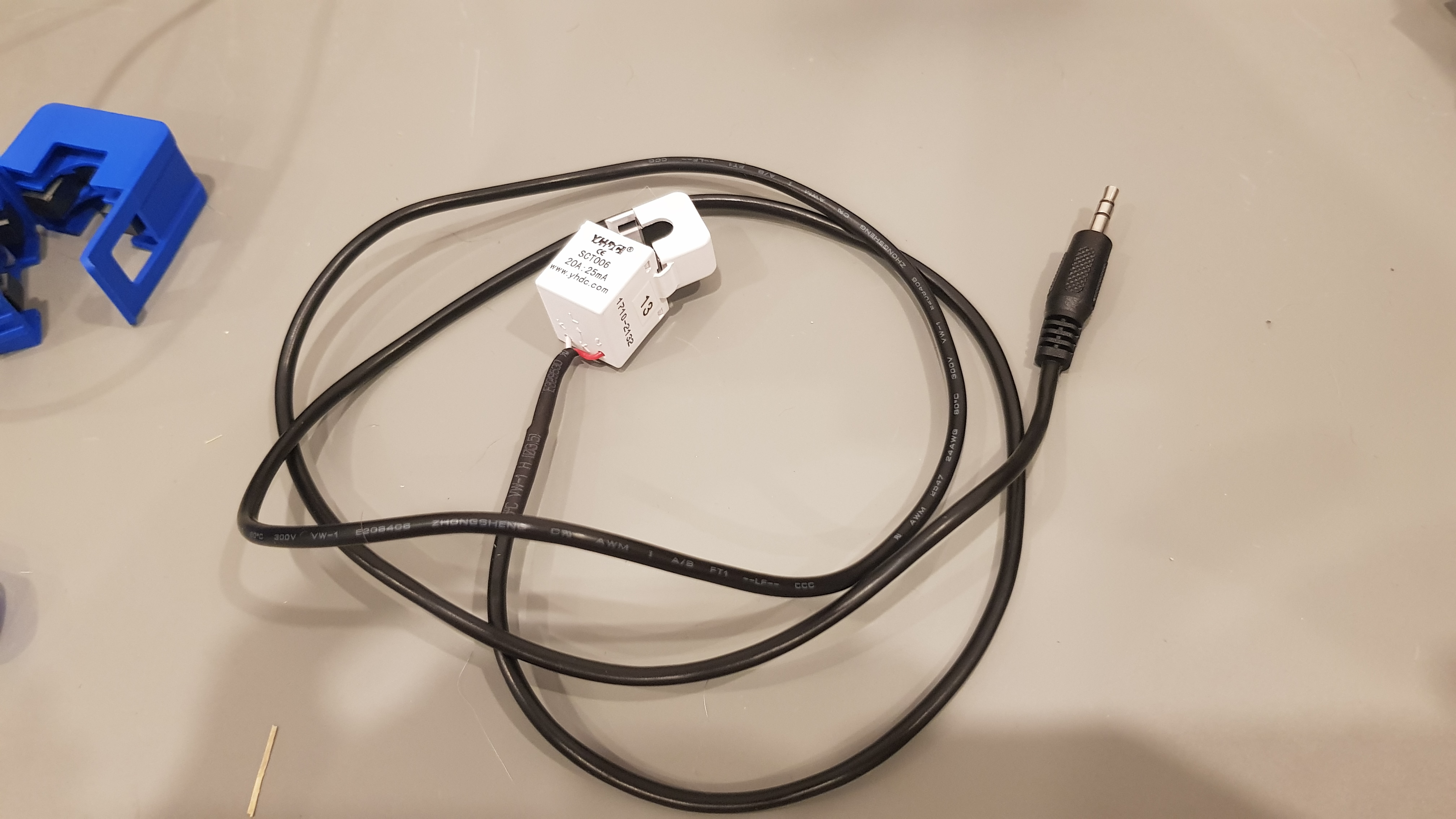
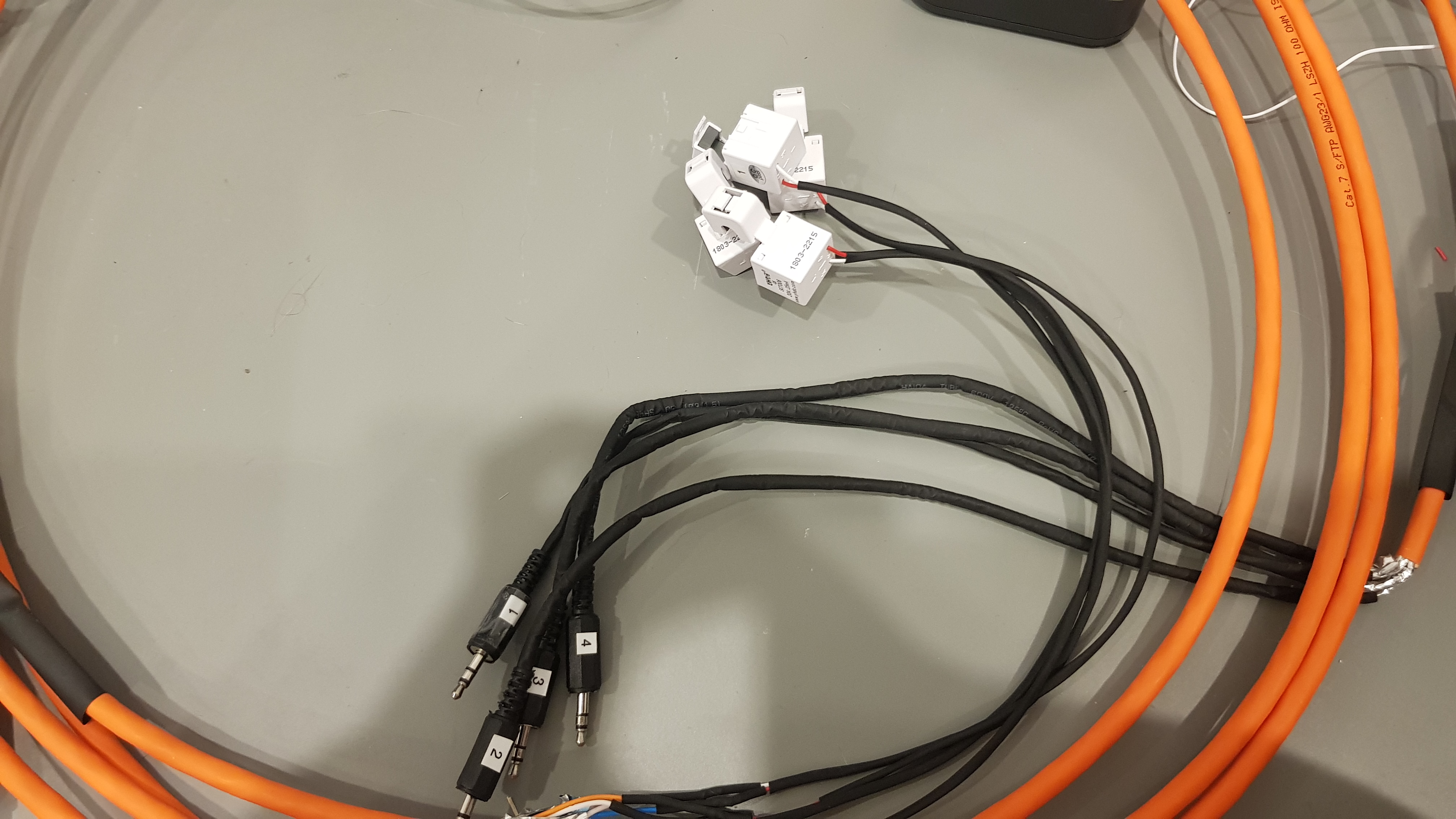
I also took some pictures of my test setup and one of the CTs:
Is there anything else I can test or do to further investigate on this problem? Are these CT’s just crap (or mine are “broken”? Are there some solid core CTs that are well suited for my application which are cheap, so I could do some comparisons? (Europe setup, 50 Hz, 16 amp circuits)
Regards,
Jan
The difference here is between 2033 and 2051 is 0.88%. Well within my expectations for these CTs.
This is interesting. I’m wondering if you used the same power strip and wire loop to measure the kettle. In the photo with the air gun, the loop puts the heads of the CTs together. I have to wonder if the magnetic field of the larger sct013 is effecting the sct006s. Since you have a reasonably agreeable power meter there, what does each of those CTs read individually when you remove the other two and test them alone in the loop?
You are right with the kettle test, I somehow messed up my numbers, overall they look quite ok. I suspected the same with the measurements. I used the same method for both tests and I also did some individual tests. That did not change anything. A single CT measures the same if measured alone or with other CTs attached to the loop!
P.S: I also checked the inputs of the Iotawatt, just to be sure. Swapping the CT to other ports does not change the readings!
Sure looks like the CTs, although I cannot explain why they seem to be accurate at unity power factor (the kettle). If I had the CTs, I could delve into it further and probably figure it out. If it were just one, I would discount the significance, but you have problems with those two. I noticed a third in one of the photos. Does that one and any others you may have exhibit the same problem?
That the IoTaWatt gives the same readings on various channels indicates to me that it is the signal from the CT rather than any problem with the IoTaWatt.
You had asked about other CTs. If you look at the selection in the dropdown menu of the input configuration display, you will see quite a few listed. Some solid core. Typically, the solid core models are the ones with phase shift less than 1.
If you are handy enough to attach new leads with a stereo jack, the HWCT004 and DL-CT08CL02 (indistinguishable physically or electrically) are very cheap give great results. I’m going to be offering the echun ECOL09-20, which is good for 40A, is solid core, and has a long lead with a stereo jack. Unfortunately I don’t intend to ship to Europe right away. You can connect with eChun directly on Alibaba. Kathy is pretty easy to work with and their prices are reasonable considering their product quality and they have CE and UL approvals.
Hi again,
I was able to pull of some more measurements today. I tried to do them in a somewhat structured manner. I tested the following:
- Different types of cables:
Self made cable with 4 CTs using Cat 7 cable
Bare CT’s connected to a 3.5mm jack using wago clamps
Original cables ordered in the open energy monitor shop with 3.5mm jacks
- Reconnecting the CTs to the Iotawatt (reconnecting the 3.5mm jack/reconnect using wago clamp)
- Reclamping the CTs to the cable
- Cleaning and reclamping the CTs to the cable
- Measure different loads:
Hot air gun
Kettle
Hot air gun and kettle at once
You can find the all measurements with the description in an excel file here. Also see the photos to get an idea of the used cables. I am still wondering how it is possible that the uniform load of the kettle seems to be quite ok but the other load is all over the place.
It looked like cleaning the CTs using iso. alc. had a negativ impact on the performance. For that reason I did only do this test for 4 CTs and not all.
Is there anything else I can measure or do to investigate this further? I only have some basic understanding of electronics, but I am willing to learn and help however possible. I have some basic equipment like multimeter and an oscilloscope. I also have some basic parts laying around.
I will have a look if I can source some of the solid core CTs, but on a first look it seems like I can only order them from china (which is ok, but will take quite a while). If possible I would like to buy some locally to check them out quicker.
I have a small number of spare CTs that I most likely will not need for my setup. Maybe it would be possible to send them to you, but I am not sure if it would be cheaper if I order some CTs from the same source for you on aliexpress. If you are interested in receiving some let me know, maybe I can fix something.
That link doesn’t work for me.
me too.
If you want to pursue this, I’m game. there’s a way to send me the raw data for analysis:
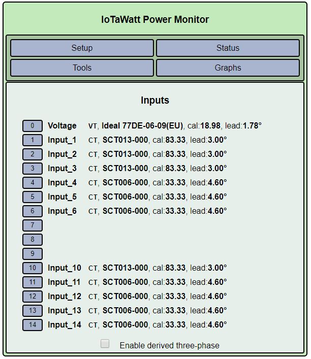
Issue the following command from a browser: iotawatt.local/command?sample=14 (obviously if you have a different name substitute that, and the “14” is the channel number which can be any of the channels 1-14.)
The IoTaWatt will return the number of samples in one cycle (about 765 for you), followed by the actual sample pairs. You can do this several times for one of the offending CTs, copying and pasting the output to a spreadsheet. Please then annotate each set with the reported power, PF and voltage at the time the samples were taken. I will also need to know the “cal” for both your VT and the CT as listed in the setup/inputs display.
With that, I can plot the voltage and current waveforms and possibly get a useful clue about what is happening.
Hi,
I will try to make the file available later. Is it precise enough if I carry over the voltage, power and pf after coping the samples? If not is there an efficient way to gather the data from one moment in time?
What kind of load do you want to see? Only the hot air gun or also the kettle and both combined?
Close enough.
Mostly interested in the hot air gun, but one with the kettle may be useful.
Thanks
Ok, I will see what I can fix this evening!
So, I did a few of the measurements you suggested. I measured the hot air gun 5 times, and the kettle twice. Between each measurement I reclamped the CT. All measurements have been done with sensor number 14, which is one that I bought from the openenergymonitor shop.
I shared the excel file here. I hope you can access the file now (also the previous one), my router has some trouble exposing my internal host. For the calibration please have a look at the attached screenshot. I used input 14 for my tests.
If you need any further measurements, info or help please let me know!
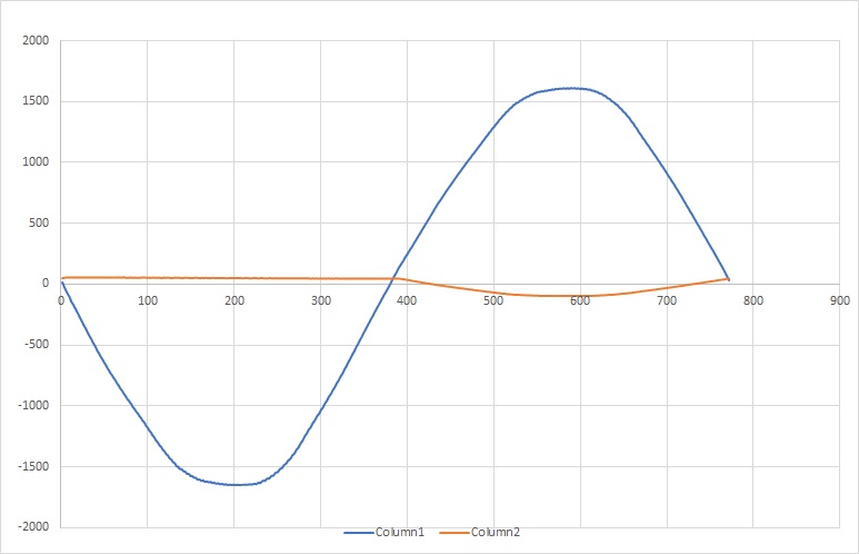
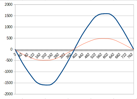
I can see why the hot air gun is not being measured properly. Here is a plot of voltage (the sine wave) vs current (the other one).
It’s not quite a true picture, because the asymmetry of the current signal throws the mid-point calculation off. I’m not an expert on how hot-air guns work, but it looks like it has some kind of control circuit that limits the power by chopping off the whole cycle when it’s had enough. Most of the circuits like this that I’ve seen limit each half of the wave symmetrically.
The effect can be mitigated by reducing the range that the midpoint can move in response to an unbalanced signal. This is something I can look into, but not a common problem.
What I cannot understand is why the SCT013 does not exhibit the same problem. So I’m going to ask that you repeat the experiment with the SCT013. Maybe two sets of data just to be sure.
BTW/ here’s what the kettle looks like:
UPDATE: I’ve taken a look at the bias adjustment code, and that doesn’t explain the problem. I am very curious at this point to see the SCT013 data.
Janecker
Does the hot air gun have a temperature control/setting or is it just an on/off control ?
@overeasy: I will try to provide the measurements for the SCT013 this evening.
@Giraffe: The hot air gun only has a simple 3 position button. Off, low, high. There is no further temperature control, but I would guess it is doing some type of temperature controle internally to limit the heat.
Can’t tell for sure without looking but with just a two position high/low switch for heat level I would not expect a particularly complex system for controlling the heat. If its like a hair dryer for example the switch would just add more resistive heating elements.
I was thinking that maybe it had a continuously variable heat output using some sort of thyrister switching circuit but thats unlikely.
The PF should be close to 1 as most of the load is resistive, the fan motor might be an inductive load but it would be dominated by the resistive load.
Sorry, I don’t have any answers. The current output graph makes no sense to me. Will be interesting to see the SCT013 version.
Just finished the new measurements with the SCT013 for the hot air gun and the kettle. You can download them here.
I created the same diagram as you did (I think) and it looks quite different.
The samples look very weird as well, but why does it a quite precise power consumption?
I was curious how the waveform straight out of the CT looks like, so I hooked both CTs up to my oscilloscope with about 30 ohm resistance in series. The first picture is from the SCT013, the second is the SCT006. If helpfull I can also export datapoints directly from the scope.
They look similar, but the SCT006 has an additional high spike on the positive side of the waveform. As I said I only have basic electronic understanding, but to me it looks like the hot air gun ist just using one side of the sine wave?
EDIT: I messed up the first measurements. I corrected this post with the new data.
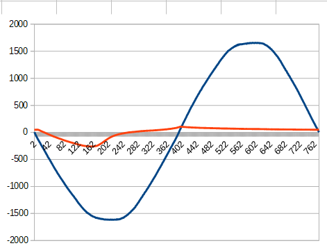
At first glance, but I think they are the same. Here again is my plot from the IoTaWatt samples:
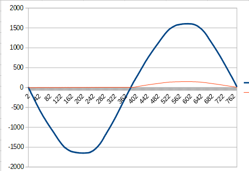
I flipped the sign so that current and voltage are the same. The CT was reversed (also in the others). IoTaWatt corrects that automatically in the power calculation. But it looks the same as yours.
What’s a little misleading here is that the SCT013 is 2000 turns (100A:50ma) and the SCT006 is 800 turns (20A:25ma). The SCT013 is theoretically less accurate, but that’s not the case here.
To reconcile with your scope, we need to increase the amplitude and squeeze the timeline, and set the colors:
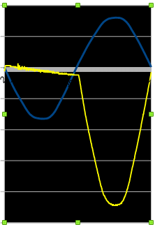
That’s pretty close to the scope output. Now the SCT006 with the same scaling and treatment:
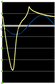
Pretty close again. I don’t think they will be the same because you are using a 30ohm resistor and although I don’t know exactly what’s going on, I know that the SCT006 has a big problem with higher burden values. IoTaWatt is 24ohm. It’s spec’d for 10ohm.
All I can say is that IoTaWatt is reading them correctly. It matches your scope pretty well. The SCT013 seems to be OK with the asymmetric loading. The SCT006 fails miserably. At this point I can only speculate at what’s going on.The “power” side of the curve looks pretty much like what happens when the thing saturates at higher currents with symmetric waves. Perhaps the saturation comes very early on when there is no polarity switch on the backside.
What I’d like to know is what’s going on exactly on the non-power side. Your scope doesn’t appear to be zero calibrated. At 5ms /division, the “1” is at about 7.5ms neg and 12.5ms positive. If I move up to where the traces are 10ms apart, it goes to positive briefly and then straight lines to zero on the other side. Sure looks like the control just lops off half the signal. I wonder if that’s how they get low and high? switch in a diode to get half power? Is this the “low” setting and if so, what does “high” look like?
So to sum up, the SCT006 seems to be working OK with symmetric loading like the kettle, even at higher current. It doesn’t seem to be able to deal with the asymmetric loading of the heat-gun, even at very low current. The IoTaWatt seems to be working OK: garbage in = garbage out.
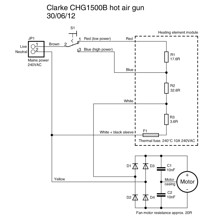
Found this circuit for a hot air gun
And this for a hair dryer