Red led flashing continuously after initial setup

I just received the IoTaWatt device. Order 126274, March 8.

After finishing the initial setup and configure all the inputs, I noticed there was not readings from the CT and VT. I checked the Led and it is flashing on Red continuously. Sincerely I cannot assure if it was like this since the first power up because I did not check the Led before.

Verified documentation and not much on Red led flashing. I did some basic troubleshoot (Restart, use a different WIFI also with internet acces, verify config.txt on a Jason). Checked Message Log and this is what I got:

SD initialized.
Real Time Clock not running.
Reset reason: Software/System restart
Trace: 9:0[10], 9:0, 9:1, 8:2[10], 8:2, 9:2, 1:2, 1:3, 1:3, 1:1[10], 1:2[11], 9:0[11], 9:0, 9:1, 8:2[11], 8:2, 9:2, 1:2, 1:3, 1:3, 1:1[11], 1:2[12], 9:0[12], 9:0, 9:1, 8:2[12], 8:2, 9:2, 1:2, 1:3, 10:2, 10:3
ESP8266 ID: 565628, RTC M41T81 (68)
IoTaWatt 5.0, Firmware version 02_07_05
SPIFFS mounted.
Local time zone: -4:00
device name: IotaWatt
HTTP server started

It is normal that the RTC is not running?
How can I solve this problem.

Thank you in advance.

The LED blinking red continuously means that it is either not connected to WiFi or has not been able to access a time-server or both. The message log that you posted does not indicate that it has connected to WiFi.

Let me try to sort this out.

Apparently it was connected at some point in the last 10 days since you received it, because you were able to configure some inputs and set the time-zone.

At some point you say that you tried a different WiFi. How did you accomplish that?

How did you access the config to verify the Json? Have you removed the SDcard?

Are you sure the VT is plugged into a working outlet and plugged into the IoTaWatt?

Thank you for the quick answer, and, of course, thank you for your help. Here you will see my answers:

It is a strange situation, it looks as if it is connected to my WIFI because I have access to the configuration web page via the IP address and a browser but at the same time I saw something this morning (you will have details at the end of the post) that brings me to have more questions.

Since the very beginning of the first power up, I had always access to the config web page. I’m able to check/modify input configurations and do anything from this web page, which if I understand correctly should not be possible if the iotaWatt is not connected to the WIFI.

Using the web config page, Yesterday I tried a different WIFI (Using a Hotspot with my phone) and problem was still there. Also using the web page, yesterday I went to “Tool ->File Manager and Editor” and copy the content of config.txt to check it online (By the way I did not remove the SD Card because I do not want to modify the file structure and bring more troubles).

The VT is plugged on a working outlet. Actually, I just measured the AC output and is at 10.79V.

After gave the answer to all your questions, here you have an update about the problem.

Last night, I left the IotaWatt connected to the power supply. This morning when I came back to check it, I was surprised to see the Red Led was not flashing anymore and it was just flashing in green continuously. Once again I checked the Message Log and I saw at some point, today around 7:46AM, it said it was connected to my network (I can assure you nothing changed on WIFI or router settings, or anything else here this morning) and initialized the RTC. Here you have the Message log for that point:

SD initialized.
Real Time Clock not running.
Reset reason: Power On
Trace: 44:208[168], 247:30[238], 205:79[227], 21:8[53], 98:146[114], 145:247[46], 57:216[194], 226:254[147], 243:123[122], 30:187[52], 169:70[144], 8:58[94], 85:167[192], 210:149[103], 59:147[210], 48:194[161], 116:125[161], 49:133[87], 203:221[35], 138:242[246], 39:244[26], 17:128[221], 59:98[198], 6:171[93], 195:22[29], 87:76[19], 239:201[112], 42:207[202], 217:70[36], 4:124[114], 248:51[1], 101:223[218]
ESP8266 ID: 565628, RTC M41T81 (68)
IoTaWatt 5.0, Firmware version 02_07_05
SPIFFS mounted.
Local time zone: -4:00
device name: IotaWatt
HTTP server started
WiFi connected. SSID=Nauta, IP=192.168.0.196, channel=10, RSSI -74db
MDNS responder started for hostname IotaWatt
LLMNR responder started for hostname IotaWatt
timeSync: service started.
statService: started.
Updater: service started. Auto-update class is MINOR
3/27/22 07:46:07 timeSync: RTC initalized to NTP time
3/27/22 08:31:39 Restart command received.

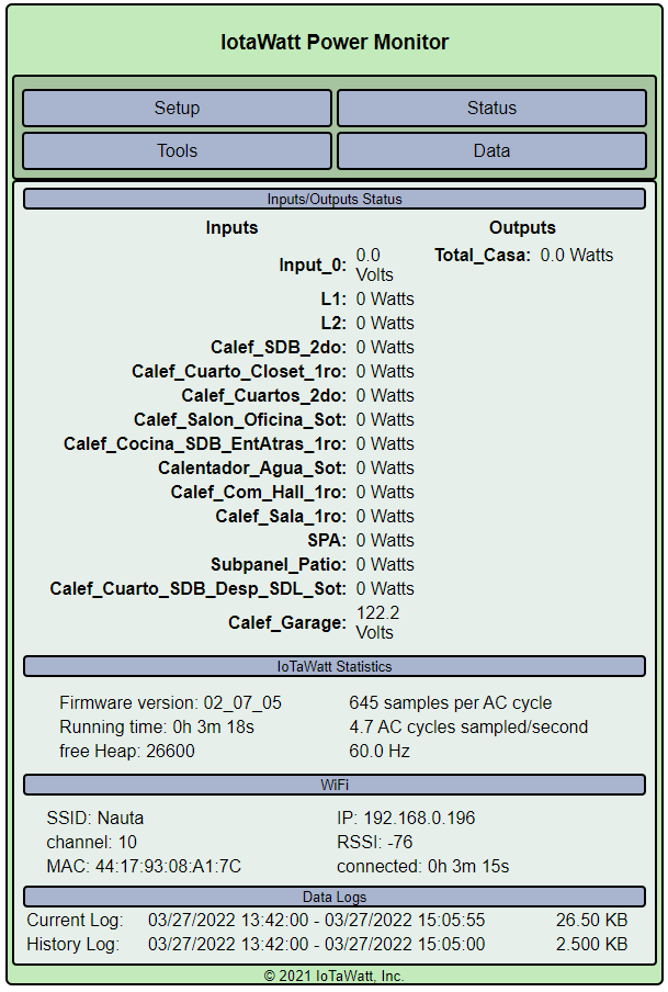
Then after that, I checked the Status and still there is not readings from the VT even when it was connected.

Today, I repeated the test I did yesterday with a different WIFI (once again using a hotspot and my mobile data connection to the internet) and even when the Iotawatt is now flashing on green continuously. I still have no readings from the VT or CT.

It seems to have the same problem because this is what I got on Message Log:

SD initialized.
3/27/22 15:25:15z Real Time Clock is running. Unix time 1648394715
3/27/22 15:25:15z Reset Reason: Power-fail restart.
3/27/22 15:25:15z ESP8266 ID: 565628, RTC M41T81 (68)
3/27/22 15:25:15z IoTaWatt 5.0, Firmware version 02_07_05
3/27/22 15:25:15z SPIFFS mounted.
3/27/22 11:25:15 Local time zone: -5:00, using DST/BST when in effect.
3/27/22 11:25:15 device name: IotaWatt
3/27/22 11:25:18 Connecting with WiFiManager.
3/27/22 11:28:24 HTTP server started

I have a lot of questions but the main ones are: How can I get access to the config web page using IP and browser if it is not connected to WIFI? Also I am curious to know why at 7:46a.m. today the device shows a connection to my WIFI even when nothing changed on my router or WIFI config since yesterday.

Once again thank you in advance for your help.

Well, what the message actually shown is that the time was successfully set at 7:46. The WiFi connection was established during the initial startup as evidenced by the connection message before startup of the timesync and stat services which only occur during setup.

Now that the time is set, the remaining issue is the zero voltage. As a diagnostic step, can you reconfigure one of the inputs 13 or 14 as a VT, remove any CT connected to that input and plug the VT into the Corresponding three-phase voltage plugs in the rear?

After that, please run the status display and see if voltage is non-zero on that input.

Thank you for your answer. I just did the test you asked me to do.

I configured the VT on input 14 and worked. I was able to see the 121.3 Volts in input 14 on web page. Then I turned back to input 0 and still got nothing.

Hi there, I do not know if it is helpful but here you have an image i just take with VT on input 14.

Now we’re getting somewhere. That isolates the problem to several components in the input_0 circuit and demonstrates that the VT is good.

The input_0 jack may not be adequately soldered to the PCB. It is a surface mount component and sometimes the reflow solder does not do a good job on that large component. There are three ways to proceed:

  1. You can send the base unit back and I’ll either repair the jack or replace the PCB.

  2. If you have a soldering iron, you can try just heating up the four soldered tabs on the jack and see if that restores full function.

  3. You can continue to use the IoTaWatt as is using that input_14 as the voltage reference.

These are not mutually exclusive. If you want to try to solder the tabs and it doesn’t work out, you can still send it back for repair or replacement.

Regarding option 3, your CT inputs should still be reading zero. If you edit your other inputs, you will see that there is a new parameter called Vref that is set to your input_0. The dropdown will allow you to set it to this input_14. If you do that, you should start to see Watts displayed.

Hi again. I just tried to solder the tabs on the jack for Input 0, and unfortunately even when I think I did a good job with the soldering iron that did not solve the problem. Sorry about that, I try to do my best on solving the problem by myself but unfortunately it did not worked.

Unfortunately I can lost an input on the device to use it as VT because I need to use all of them in my home panel. I have around 35 different circuits (Breakers) on my panel, is a very old installation and apparently circuits distribution was done by previous owners. That’s why I would like to be able to supervise the most possible in order to optimize the cost I am paying on electricity, so with the 14 inputs I already have i am still short for all my house.

On that case, I would prefer to send my device back. Please can you send me the instructions I will need to follow to continue with that process.

By the way, I would like to thank you again for the wonderful support you have provided so far. Even with all the troubles I had so far, i’m still happy I made the decision to go and get the Iotawatt.

1 Like

I understand, thank you for trying. I will advise what the problem was when I get it back. Please send to:

IoTaWatt, Inc.
92 Sewall Rd.
Wolfeboro, NH 03894

Origin is USA for base unit for any customs declaration so covered by USMCA. Will return promptly.

1 Like

Hello there, I am preparing the IotaWatt to be sent tomorrow to you via UPS. But before that, I would like to clarify some questions I have. The first one is regarding this text:

What does that mean, I am sorry but I do not know much about logistic terms. Also I would like to know if I need to mention or put something special on the box label when I will go to UPS to send this to you.

The other questions are,

  1. Should I have to pay the delivery service from Canada to the address you mentioned before? If so, will I receive a refund for that amount?
  2. I paid around 60 USD to Canadian customs for the Iotawatt (and accessories) importation when I received it. Now, I will send it back to you to be repaired/replaced. When it will come again to Canada, should I need to pay again to Canadian Customs? If so, will I receive a refund for that payment?

Thank you in advance.

Do not send UPS please. Standby while I look into this.

You should not have been charged Canadian customs on these items. There is no duty on these commodities in general and moreover they are covered by USMCA (US, Canada, Mexico trade agreement - nafta 2.0). You were probably charged $10 brokerage fees plus provincial and national sales taxes. You should have a receipt for that, if you feel it is out of the ordinary, post a copy in a PM (Private Message).

I will send a replacement circuit board by USPS. You should not be charged brokerage fees and the value should be de-minimis for taxation. I may include a label for return of the old PCB, still looking into that. This doesn’t happen very often.

Hi again,first of all thank you for the message.

You are totally right about that. I double checked the documents and I paid only for provincial and national taxes with a plus for brokerage fees. So that part is now clear for me.

Also I would like to add that, if is better for you; I can use Canada Post instead of UPS to send you the old PCB. Please just let me know what is the best option for you (Canada Post or UPS) and I will follow your instructions.

Regards and once again, thank you for the great service you are providing to customers.

Hi there, do you have any update about this. It has been a week since last message.

Thank you in advance.

Sorry, replacement will go out today.

Hello there. I just like to let you know I received the replacement a week and a half ago. Unfortunatelly I did not get the label to return the old PCB as you mentioned before.

Please let me know if you still want me to send you the defective one and on that case how to proceed.

Regards,
Mario.

I could not produce an international return label. Please discard the old PCB.
Thanks.

Thank you very much for your answer and for your excellent service.

1 Like