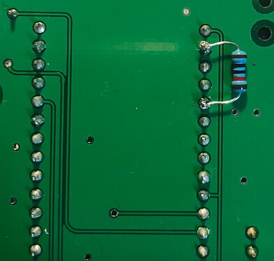
I have built 2 Iotawatts using the Gerbers for V5 and both have the same issue of the log showing “Real Time Clock not starting”.
The log shows as follows:
SD initialized.
Real Time Clock not running.
Reset reason: Power On
Trace: 246:54[240], 67:161[166], 10:235[141], 27:56[165], 159:189[235], 253:88[187], 36:185[30], 102:78[65], 169:149[121], 221:130[243], 110:207[242], 182:105[64], 73:29[159], 41:254[14], 187:183[255], 94:8[253], 53:191[253], 225:88[169], 172:21[167], 55:158[180], 48:83[209], 87:76[132], 236:252[90], 108:228[249], 25:10[29], 179:96[60], 83:26[12], 111:50[18], 20:24[227], 21:177[138], 65:243[219], 120:165[87]
ESP8266 ID: 1625747, RTC PCF8523 (68)
IoTaWatt 4.x, Firmware version 02_07_05
SPIFFS mounted.
Local time zone: +0:00
device name: IotaWatt
Connecting with WiFiManager.
HTTP server started
Faultfinding:
RTC battery is new and measures correctly
Red light is glowing faintly and no fault codes displaying
Continuity checks have been made for all paths and are OK
I am located in Australia and I see there have been NTP issues here, but I don’t think this issue is related as the RTC has not started.
When I built the units, I inadvertently had the crystals the wrong way due to the weird markings which means that the oscillator inputs to the RTC chip were S/C. I have reversed the crystals, but there has been no change, so have I wrecked the RTC’s by this error?
Further question: The log above shows as IoTaWatt V4.0, whereas the boards are V5.0 but I can’t see that this should make any difference as the circuitry is identical in this area on both V5 and V4 boards - is my assumption correct?
Any assistance is appreciated.
Regards,
Dave

