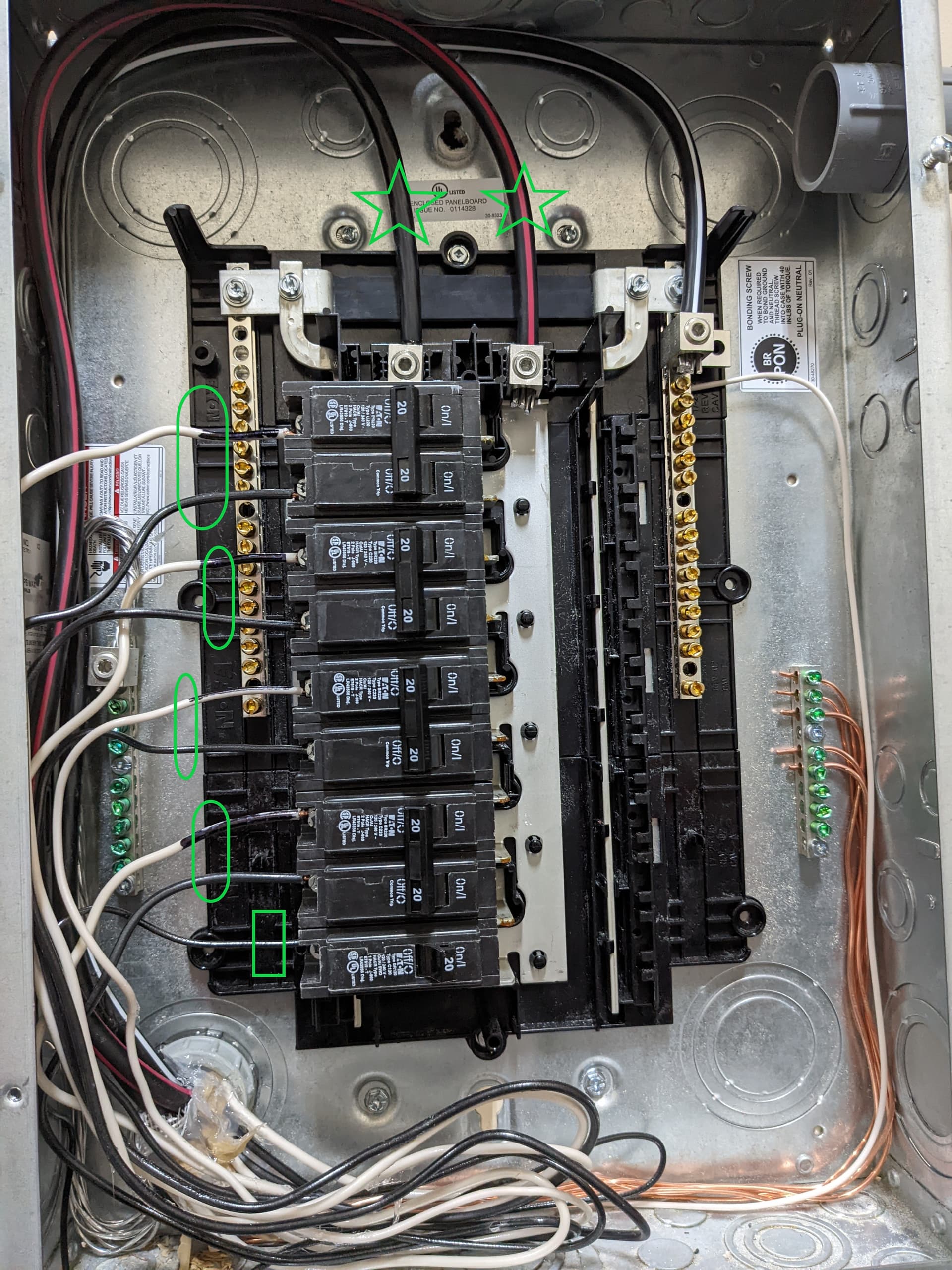
Just got my IoTaWatt in and I’m super excited to wire it up. I was hoping you fine folks to could look over my plan and make sure I’m doing it right (United States residential service). Here is a picture of my load center:
This is a subpanel fed from a 100amp breaker from my main box. I plan to:
Install a 100amp CT on each of the “mains” coming into the box marked with a green star
Install a 50amp CT on each of the pair of wires marked with a green oval. These circuits are each 20amp 240 volt circuits and I want to ensure I measure the power as accurately as possible so not looking to measure one and double it. Do I need to twist things around so that one wire is being measured in the opposite direction or am I ok to just clamp them as circled?
The bottom square circuit is a simple 20amp 120v so I just need to slap my remaining 50amp CT on that single wire.
I’m happy to answer any questions to clairify but this all seems pretty straight forward with the exception of ensuring I measure the 240v circuits properly. Thanks in advance for all feedback!
The “oval” 240V circuits are two-wire. This is evident by the use of 12/2 wire, the black tape applied to the white at the breaker, and the single neutral wire on the neutral bus (the 120V circuit).
The current on each of the conductors of a two-wire circuit is exactly the same. There is no loss of accuracy by using a single CT on one of the conductors and using double. In fact there is an advantage because the IoTaWatt will then know it is a 240V two-wire circuit and report the correct Amps.
Just so I’m clear, there’s no chance that one wire in that circuit could be pulling more amperage than the other? I can literally just clamp one wire of each pair with a single AcuCT-H40-50 and get 100% accurate reading? I’d seen another post where someone was saying that you’d need to loop one of the legs(?) to get current in the opposite direction to have the ct sum things properly.
Oh and 1 followup. If I wire everything up but don’t power the IoTaWatt right way (or if it loses power since it’s going to be on a shared GFI circuit) is that likely to cause any problems? I’d seen where you’re supposed to ground(?) the CTs if they’re going to be attached to the circuits but not plugged into the IoTaWatt itself. Is plugging them into an unpowered IoTaWatt sufficient for that purpose?
With a two-wire circuit, the current goes to the load on one conductor and returns on the other. Current is constant in a circuit. What you are referring to in the other post is a three-wire circuit. For those you need to measure the current in each hot lead and add them. You don’t have that, you have two-wire 240V loads.
It’s true that current transformers need to be “burdened” or they can produce very high voltages and damage themselves. The AccuCTs have diodes that burden them if disconnected and protect against high voltages. Also, if the CT is plugged into the IoTaWatt, it is burdened by the IoTaWatt regardless of whether it is powered up.
Just wanted to circle back, overeasy. I set things up exactly as you’d indicated and it’s working flawlessly! Thanks for the info and confidence boost!