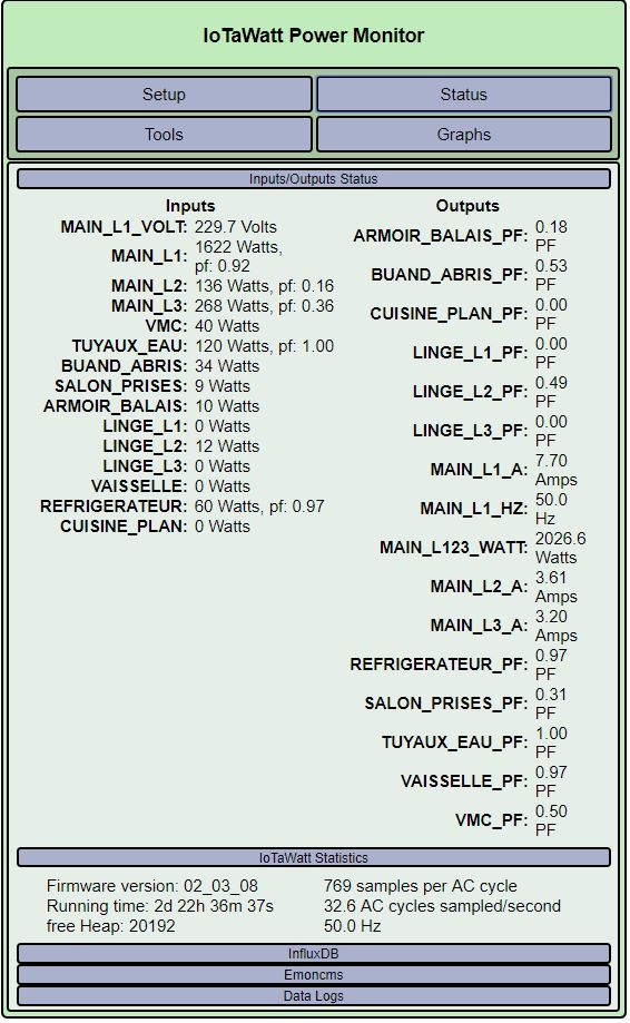
Total consumption in Watt (some 5% more that official counter)
->UPDATE: After correcting the calibration (measured with FLUKE 87) I have ~1% difference only
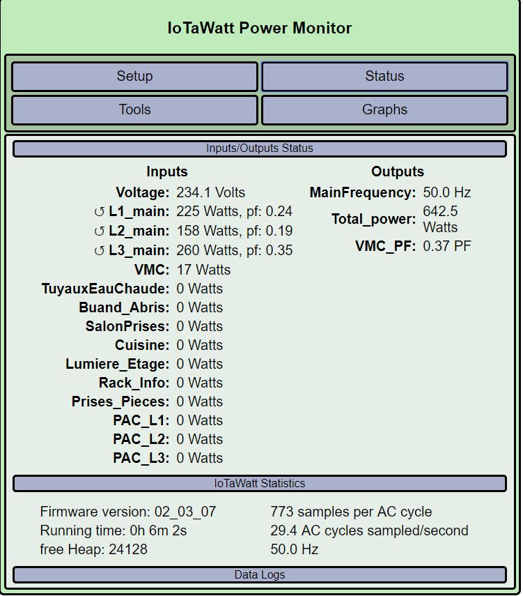
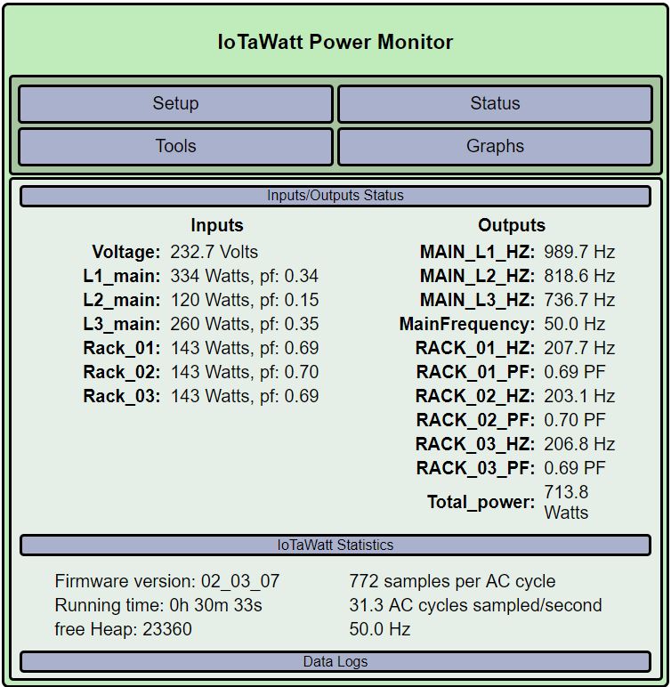
What looks strange to me:
The status informs about inverted CT
The PF looks bad…
I placed an energy power meter to the VMC, it is telling 33Watt and Phase 0.99 - 1.00, but there is is reported 17W and PF 0.37
What I verified:
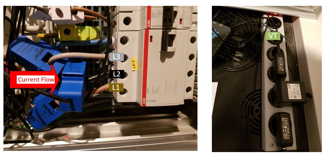
The CT of the main are mounted like that by looking the symbol on the CT : Main > Switch on my installation
When I increase the consumption of the VMC I see L3_main (PhaseC) value increasing. Therefore I think that I selected the correct Phase for the VMC.
I placed a light and switched on/off on the same plug where the reference voltage is connected and I saw the L1_Main (Phase A) power changing. Therefore I think that I placed correctly the Voltage Reference
I verified the cable colors coming from main and I associated the L1 (braun), L2 (black), L3 (grey) respectively to input 1,2,3.
NEXT STEP:
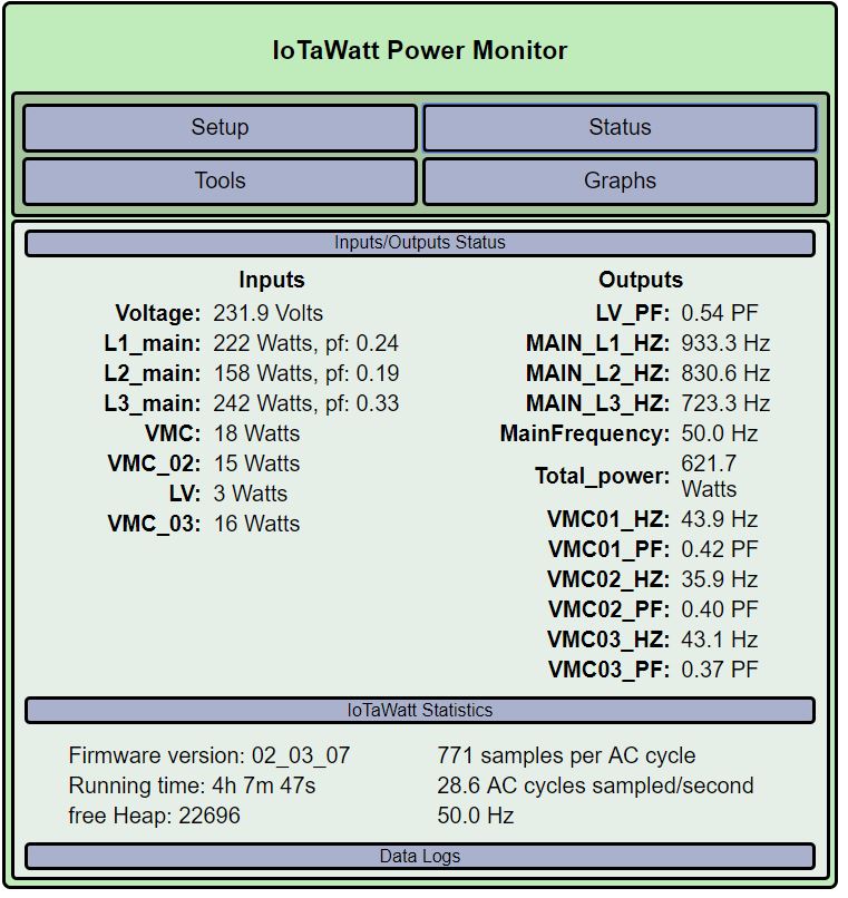
I tried to make happy the IoTaWatt regarding the direction, I connected 2 additional CT on the same cable and look what is going on with the Hz, PF and Watt differences (VMC and VMC02 are SCT006, the VMC01 a SCT019)…
Look also at the Hz values of the MAINS…
Anecdotally that’s what others have been reporting, so good start there.
The “inverted” CT symbol means that the reported power is negative and IoTaWatt has changed the sign. So there is something wrong.
I agree, those PFs, at that power level are probably wrong.
That’s helpful information. While I’m not particularly confident in those SCT006 CTs, what you are measuring is half the power. That is exactly what should happen when the wrong phase reference is specified. So either it’s the wrong phase, or it’s backwards. I suspect backwards.
You can’t go strictly by the symbols on the CT, as it’s relative to the orientation of the reference voltage. As I understand it, the Euro plug is reversible. It’s important to orient all the CTs the same with respect to the Line/Load, but that would just mean they would all be correct or backwards.
That does seem to indicate the VT is on phase 1, but I’m not convinced as the PF is crazy. I need to audit the math for that, and I’ll get to that tonight.
In the meantime, could you try either reversing the VT in the socket, or reversing the three mains CTs. If you choose to reverse the VT, you will probably need to also reverse the VMC CT. After you do that, could you post another picture of the status display and any related reference data you might notice.
The key to doing derived reference is to get the phase A working accurately. There is no difference between single phase and three phase when it comes to phase A, so it’s a straightforward problem to get right. Once phase A is good (power, pf) then the rest can be diagnosed by how they relate to phase A. Full disclosure: I don’t have a three-phase power system at my disposal to experiment, so you’ll have to bear with me as I work through this issue.
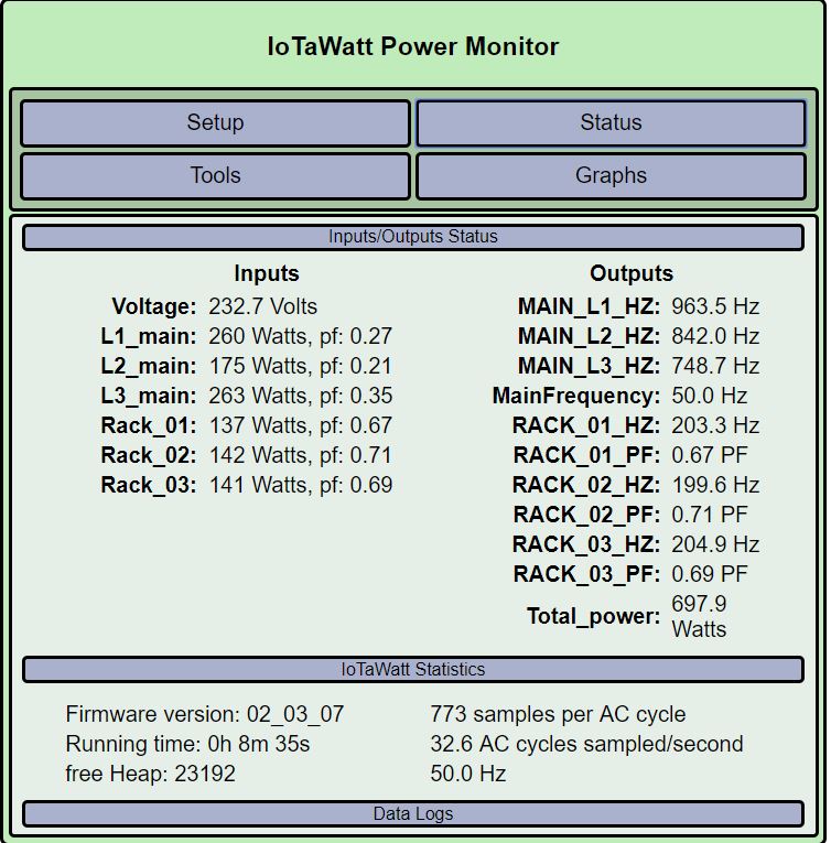
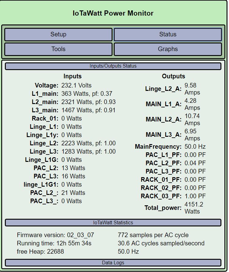
I now connected the 3 CTs to a load that should be on the PhaseA.
I measured delta voltage from L1 on power plug and main_L1 = ~97V and between main_2 and main_L3 I have 400V.
I moved the power measurement to the rack, it reports 155W and PF 0.79.
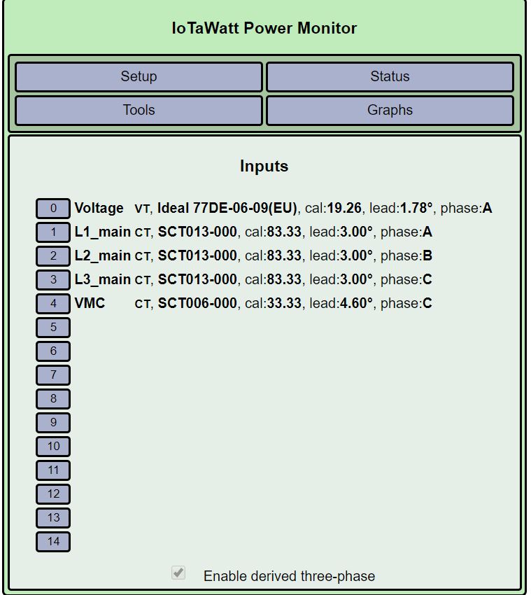
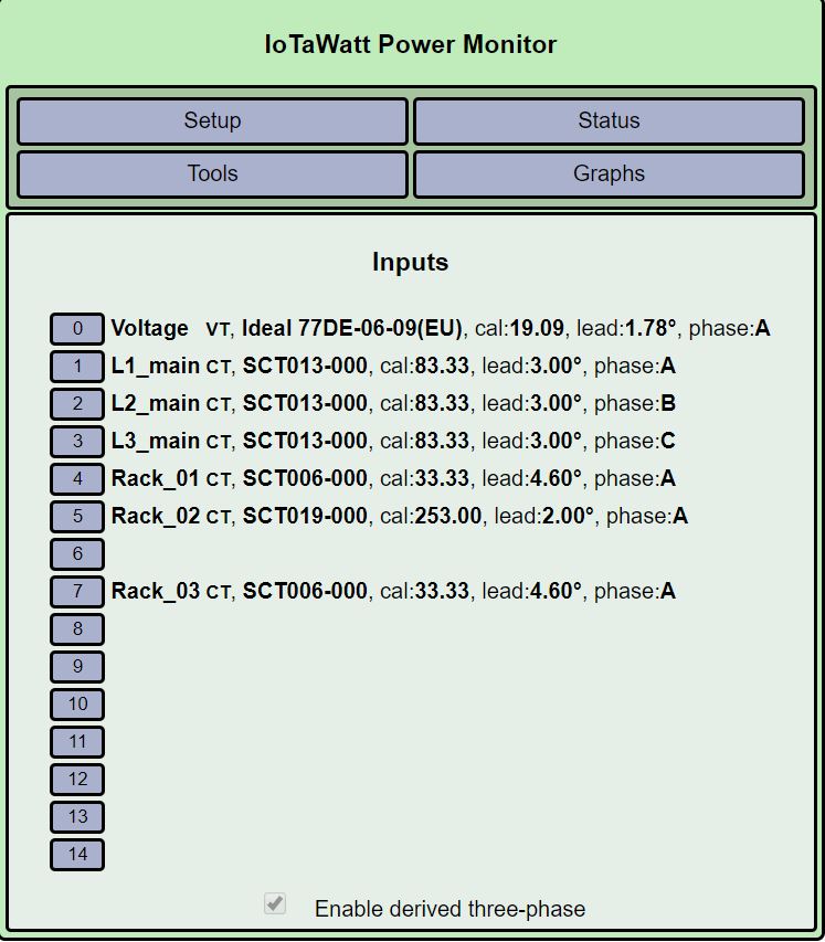
There you have the setup and the status:
You are changing too many things for this to be useful to me in understanding what might be wrong here. I was hoping you would do what I had asked and only what I asked.
Moving forward from what you have just done, I am looking at the results for the three CTs on the “Rack”. You seem to be saying that you have another power meter that shows 155Watts with .79PF for that load. That is close enough to 143 Watts and .69 PF to believe it is the same circuit with the same reference voltage. The RMS current on that circuit appears to be about 0.88 amps. That is a very small current, and the CTs you are using have their own unique challenges with that low current. The two SCT006 CTs have very large and variable phase shift at the low end, and could account for the difference in PF and possibly Watts. The SCT019 has better phase shift characteristics, but 0.88amps is only 0.4% of it’s range.
What you are seeing is possibly the result of low end phase shift compounding the already significant phase shift of about .79 that your other meter shows. I have no idea the accuracy of the other power meter in these circumstances as well.
So I am going to recommend that as a starting point, we try to measure the power and PF of a completely resistive appliance. A heating kitchen appliance like a toaster, coffee maker, frying pan or crock-pot would be good. The more watts the better. I’d also like to use an SCT013 to do that measurement, even if you need to remove one from one of the mains.
The goal is to get a measurement with PF 1.00 that agrees fairly well with your other power meter. You could also put one of the SCT006’s on the same circuit to see how it compares with the SCT013.
I just noticed the additional edits to the first post, which I had not seen before. Hz units are only valid for voltage channels, as in MainFrequency output. Without getting into a complicated explanation, the values you see as Hz for the power channels are actually the VA (rms-volts x rms-amps) These should be accurate for all phases because it is not phase dependent. They look to me like CTs, measuring marginally small loads, with an incorrect phase reference.
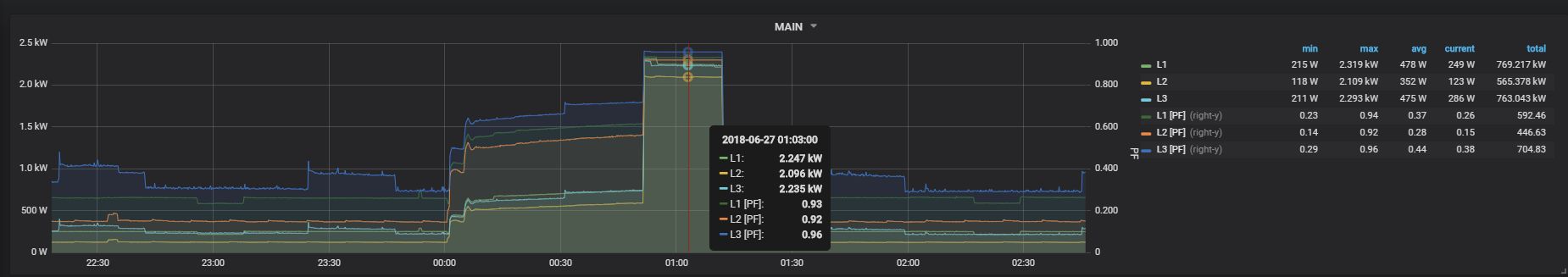
What I did not report is that I tried for the 3 phases to put a vacuum cleaner.
For all the result is similar, see the one for Phase A.
You can see that the MAIN_L1 goes to PF 0.92.
From 00:00 to ~00:50 where the heat pump is pushing the water to 55°C
From ~00:50 to ~01:10 where the pure electrical component is making the step from 55°C to 60°C (as they tell that the heat pump is not strong enough to make it alone)
When we have load looks like that the PF is ok (If my interpretation is correct).
Now the question is why at “low” energy consumption it is really low PF.
No matter how many of these anecdotal scenarios are presented, there are simply too many variables and unknowns to draw any conclusions. With derived reference, it’s not just six possible combinations of CT and phase, there is the orientation of the CT, which is itself a 180° shift. So 24 different possible combinations. The only way I know of to work through this is to use pure unity power factor loads one phase at a time to determine if a CT is assigned to the correct leg and if it is reversed. It can be a tedious process, but I know of no other way.
When you see a power factor of .23, that means that the real power being measured, which takes into account phase shift, is 23% of the apparent power being measured, which is not affected by phase shift. That’s hard to do if the phase reference is correct, but once the phase reference is wrong, and it typically is wrong by around 60°, the real power factor has a huge impact on the calculated power factor. All that can be compounded by the non-sinusoidal nature of the non-unity load.
So if you want to get a strictly resistive appliance with the ability to put a CT on one of the conductors, and do some highly controlled measurements that eliminate all of other variables, we might be able to figure out what’s wrong. Otherwise, I cannot help you.
There I measured the tension between:
L1 and VT = 96V
L2 and VT = 403V
L3 and VT = 403V
Some additional questions:
A) Can I assume that I really have the VT connected to the supposed L1?
B) Can I assume that the current flow is the one coming from the Main Big Cable to the switch ?
C) The arrow on the CT currently is set as my red arrow, but this direction symbol is for the current or of the electrons (as it is the opposite) ?
I don’t really understand how 97V can happen, but probably is related to this problem. It’s all academic to me, and I can’t see where any of the usual suspect phase differences would result in 97V between two phases.
The IoTaWatt calibration is inline with the nominal 230V, so the VT appears to be seeing ~230V. I’m curious now. What are these voltages:
Regarding the L1-VT I measured at the not used plug,I do not remember really, I would have to search, but those effects when no load is there could be due to the voltmeter internal resistance…
No, that’s another effect. It does not matter whether the load is connected to the socket or not. If you measure between L1 in the fuse box and L1 at the socket, then this is the same line and that means there should be no voltage difference at all. It is the same effect if you measure with both probes of the multimeter at the positive pole of a battery, also here the multimeter shows no voltage difference.
Do you have any other sockets you can use for the voltage reference?
Since the voltages from the socket used for the voltage reference to L2 and L3 seem to be correct, the socket actually seems to be connected to L1. This would mean that you do not measure on L1 in the fuse box.
I think that I really measure L1, as I put the point on L1 like picture of previous post.
When I measure the L1 and the Phase at the Fuse where this plug is connected I see 17V.
I tried to measure the voltage between L1 in and all the other fuses using it and I have different voltages e.g. 7V, 17V…
There must be some effect somewhere…
 Thanks a lot for your support!!