Hello,
new to this. i bought an iotawatt thinking that my panel is like any other panel i’ve seen until i was about to install and … surprise!!! hahahaha.
so i’m wondering if anyone has been able to install to this kind of a panel before?
hopefully i can attach pics…
i bought iotawatt bec i wanted to install Solar soon and i wanted a better picture of my usage during the day.
if anyone can please advise me a safe way to install the CTs with this panel?
the mains in particular?
would be much grateful and appreciated!
i cant remove the meter without contacting the local Electric company and i dont really want to do that 
Thank You!
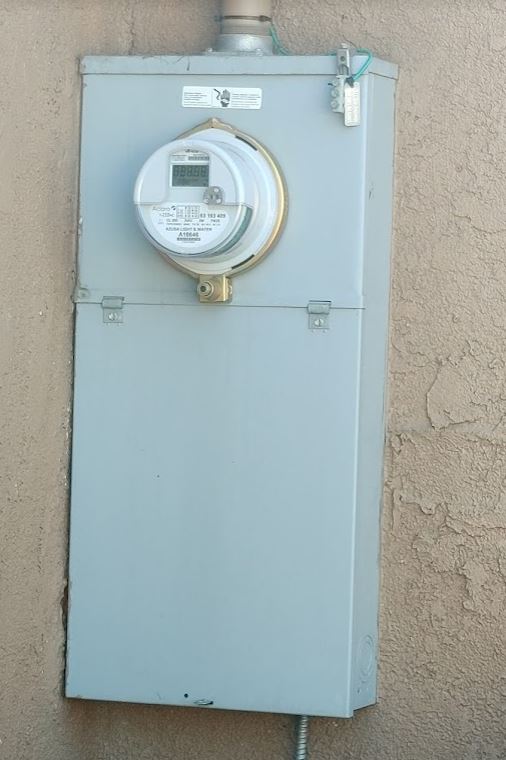
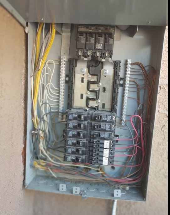
and apparently, the insides look like this…
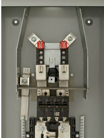
this model, if i’m not mistaken is a
Siemens MC2040B1200S 20 Space 40 Circuit 200-Amp Surface Mount Meter Load Center
You might do some changes in the main bars, however it is not recommended since you will void the certification of the Panel. Depends on where are you located it could be a deviation finding for any inspector that will trigger an investigation. You might opt to install a secondary Auxiliary Panel right at left or right side and move all your circuits to that panel and use a main circuit breaker installed in the existing bus bar to feed the secondary Panel…
Once you install a Main Distribution Breaker you can install the two CTs at the cables going to the Auxiliary panel.
Or Just replace the entire panel… one panel meter and one distribution panel… The Cheaper solution Incan suggest is to install a side distribution panel feeding it from a Main Breaker from the existing panel… Since the existing panel it is 200 A, you might use a lower rated panel If you just use 100A total in your installation… the side panel and main breaker might be for 100A.
It is not recommended to touch the existing fedding panel since that will possibly mean a new total recertification… involving submitting a revision to your electrical company.
You should take in consideration the size of the panel. I recommend to use an Auxiliary Panel big enough to ensure your CTs are properly allocated avoiding any possible electromagnetic interference. You will probably also need a second control panel to accommodate the IoTaWatt and all its components, nicely and comfortably.
I suspect that this panel is an outside panel, away from you main Network router… That distance is something to consider to have the proper Signal Strength to connect the IoTaWatt to your local network so you can Access the data anywhere inside your home…
From a strictly physical point of view, the meter appears to be fed by cables with room for CTs. The top of the metal separation plates appear to have a corner cut that would allow the CT cables to run up and then down into the lower box.
At issue is removing the meter to do that. I don’t see a seal on the meter, but even so, if you don’t have experience or permission to remove it, I can’t recommend it. You might try shopping those photos to a few electricians and see if you can get one to swing by and install the CTs. They usually have a relationship with the utility and can get it approved and resealed.
Seal is there… That is a new type of Security sealing clamp… Only Authorized personnel should have that security key.
Of course, you always can find someone having the authorized key… but that is illegal depending on where the installation is. Breaking in a Meter is illegal…in most part of the world.
Installing the CTs Before the Meter, in the main supply cables, is also considered a violation.
Thank You for the responses!
i kinda figured that contacting the EC is the best way to go about it. the worse case is they say “no”.
either way. when the solar comes. i should have some CT installed. i’ll just use it for the rest aside from the mains.
Cheers! will update someday when the Solar is installed.
I suggest to inspect and revise or update your Mechanical Ground Cable. I seems to be in a non compliance with the current Ground rules using a Ground Bar… The terminal Block where it connects is not correct… The wire size appears to be improperly sized… Just by looking at your picture…
This days the mechanical Ground Cable going to your Ground Stud in the Dirt or Ground, shall be capable to conducting the same amount if current of the main breaker… If your main Breaker is 100A, the minimum size fir ground shall be 100A rated, or Size 2 AWG… Looks like you have a 8AWG… Jus to ensure the safety of your beloved ones… and to conform the new inspections and certifications and to protect your property of any fire caused in an Faulty Transformer serving your house…
You might have another option, Depending and consulting the Box Manufacturer, You might remove the bars and substitute by cables… That will require to installed new terminal blocks in the studs rated to 200A. Also the cables must be rated to 200A. Except we are assuming that this panel is 200A and it is really rated to 100A… if it is rated to 100A then the cables should be rated to 100A or 2 AWG and the terminal block rated to 100A for at least 2 AWG. Of course all this modifications are the ones I was referring to at my first post. You Probably will void the manufacturer UL Certification…and hence might be found in violation in case of any accident or fire… you will be liable. and responsible… for any damage caused to third party, to your property, to your beloved ones, or to any Electric Company officer or worker that result with injuries or death caused by your modifications… That is why I oot to recommended you not to proceed with any modifications to the existing panel… For me that’s a highly risk move than can end very badly…
Thank You Guaitiao,
i havent touched this panel since i moved in 7 + yrs ago. the previous owner was the one who upgraded it to 200A. but when the solar install proceeds, i am sure the local inspector will let me know what modification we will need to make. God knows they are such pain that they walk around with bullet proof vests… i dont envy their occupation.
i’m technical and if i know the specs required, i usually follow it. Thank You for calling that out.
There are some CTs specifically designed for Busbars… At least for ABB and other mew generation Panels and Meters… I think your panel do not have the space for even those.
You can consider an opportunity to upgrade your system and include an Emergency Power Generator Transfer Switch or service panel. In that way you could use you PV system, Utility power and a manual transfer for a Backup Generator in the future. If you have to do some modifications, I suggest to you to consider add the required service panels to transfer your power to a backup generator.
Also, it is good Idea, to wait until you have all components for you PV system and you can read If you have selected the proper hybrid Inverter you might not need an extra service manual panels for a Back Up Generator… Since, usually a good Hybrid Inverter comes with the Generator Hookup Options…and it will serve as an automatic Transfer Switch control for a Emergency Back up Generator. Things to consider…
I’m planning for a enphase system. i probably will get someone to install it for me.
in our city, i need permits and licensed electrician to install so its not much of a choice
i dont know what the solution will be for this particular install. when i find out. i will try to get everything done so its easy to add these later.
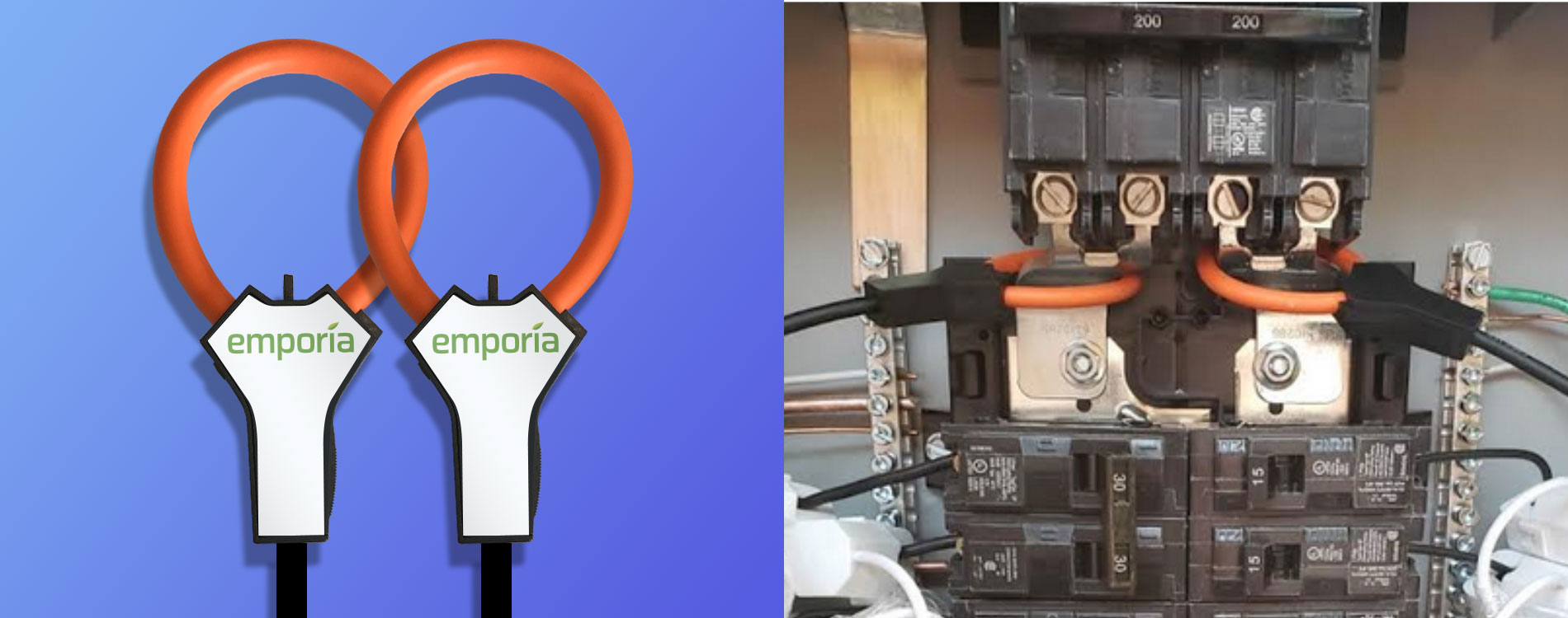
Thanks for the suggestion of busbar CTs! for this particular panel, i found this solution.
would you know if this will work with the iotawatt module?
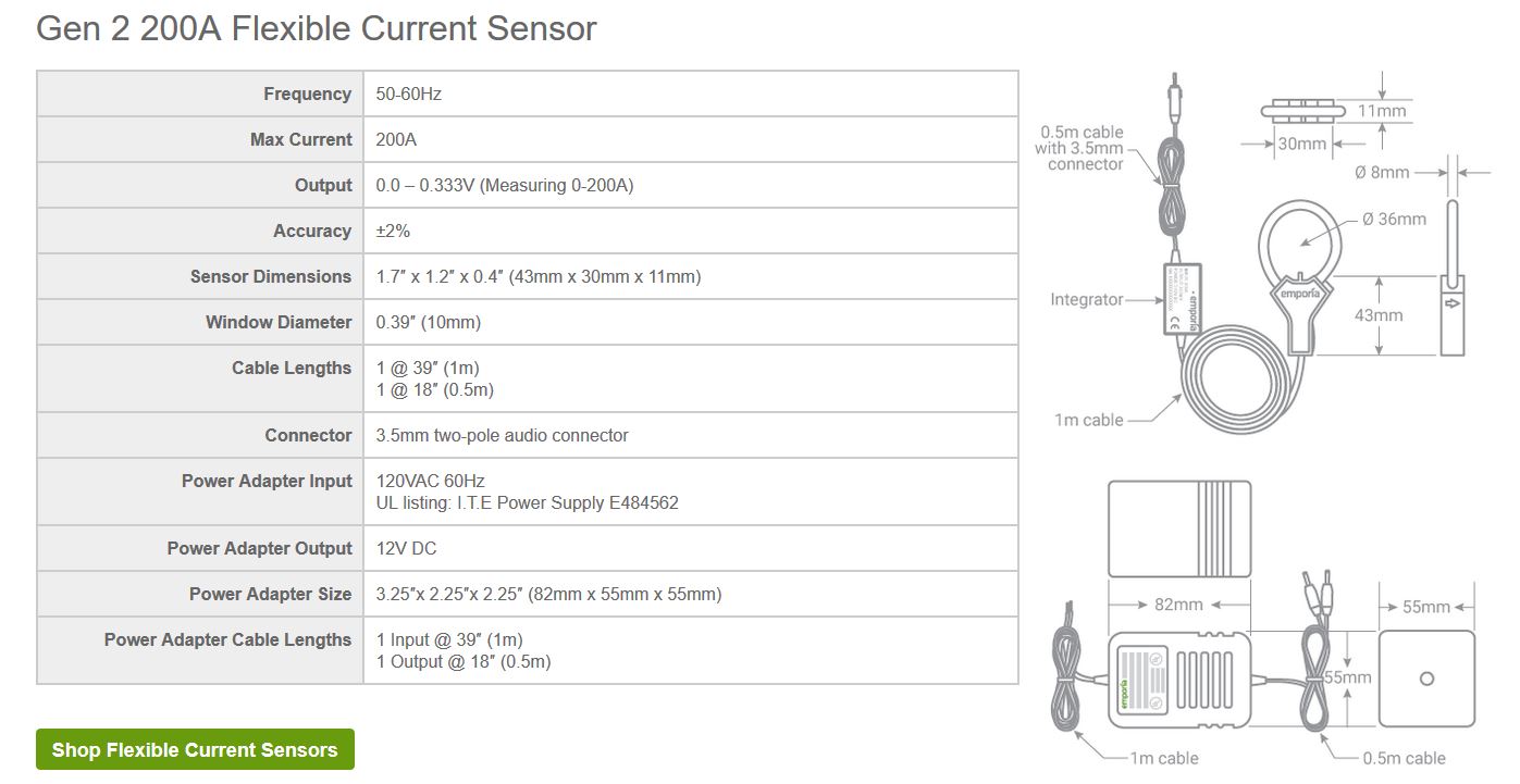
found some specs. do you think this would work? price is relatively ok @ $59
looks like it could work… @overeasy what do you think? anything i need to tweak possibly? i dont have much options…
i looked at their offering and while it looks like its similar to iotawatt.
i dont like the idea of giving out my personal information just to use the device. probably why the price is so low.
I don’t think that would work with IoTaWatt.
ah too bad… hopefully, iotawatt will have something similar someday.
in the meantime,
I’m going to go ahead and do the ones i can. i got to find out whats using so much electricity…
Installed with 6 CTs for now. already found a few things i need to fix. Thank You IotaWatt!
@overeasy
for the 200A CT i need. do you think this
plus
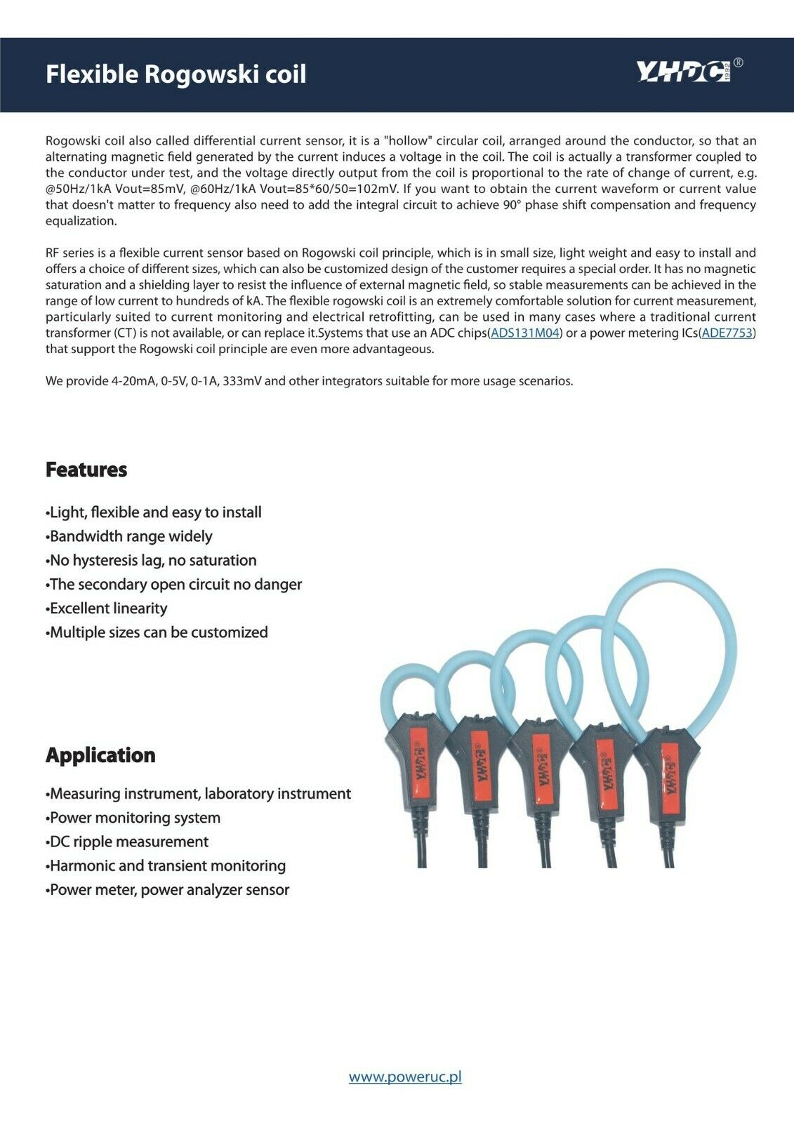
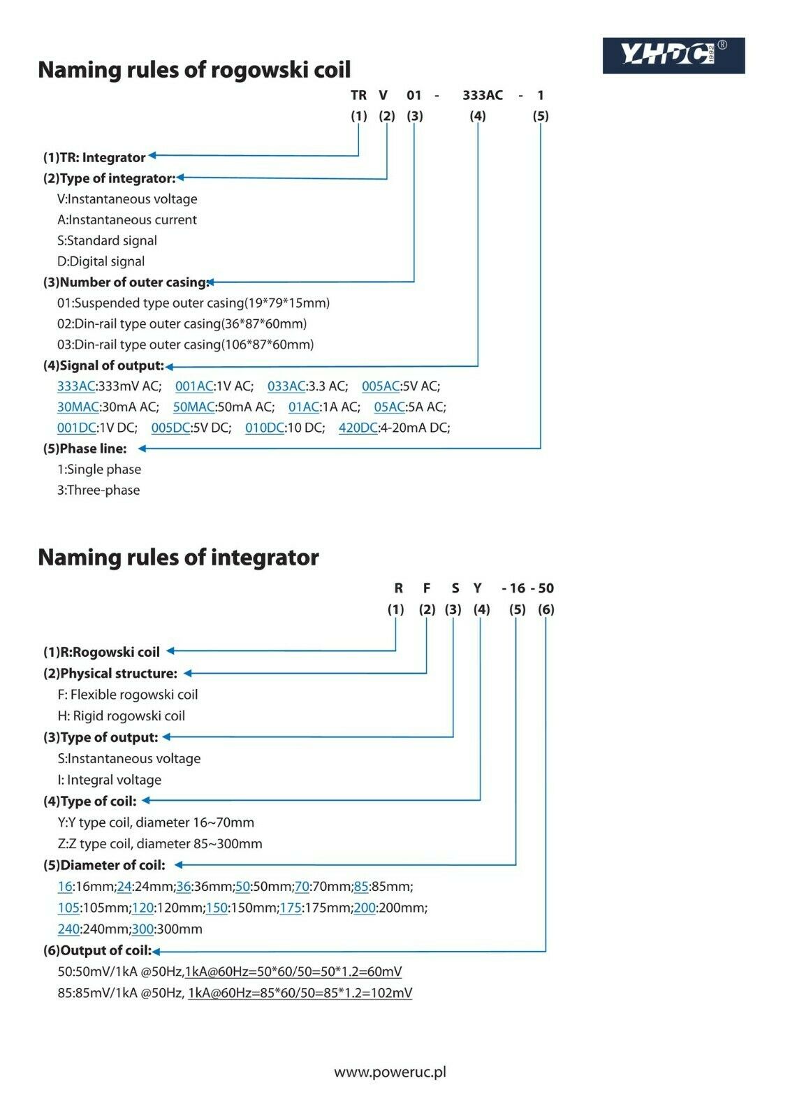
YHDC Rogowski Coil integrator TRV-01 input 100-6000A output 0.333mV/1V/3.3V AC | eBay,
appropriately picked, would work?
Thank You.
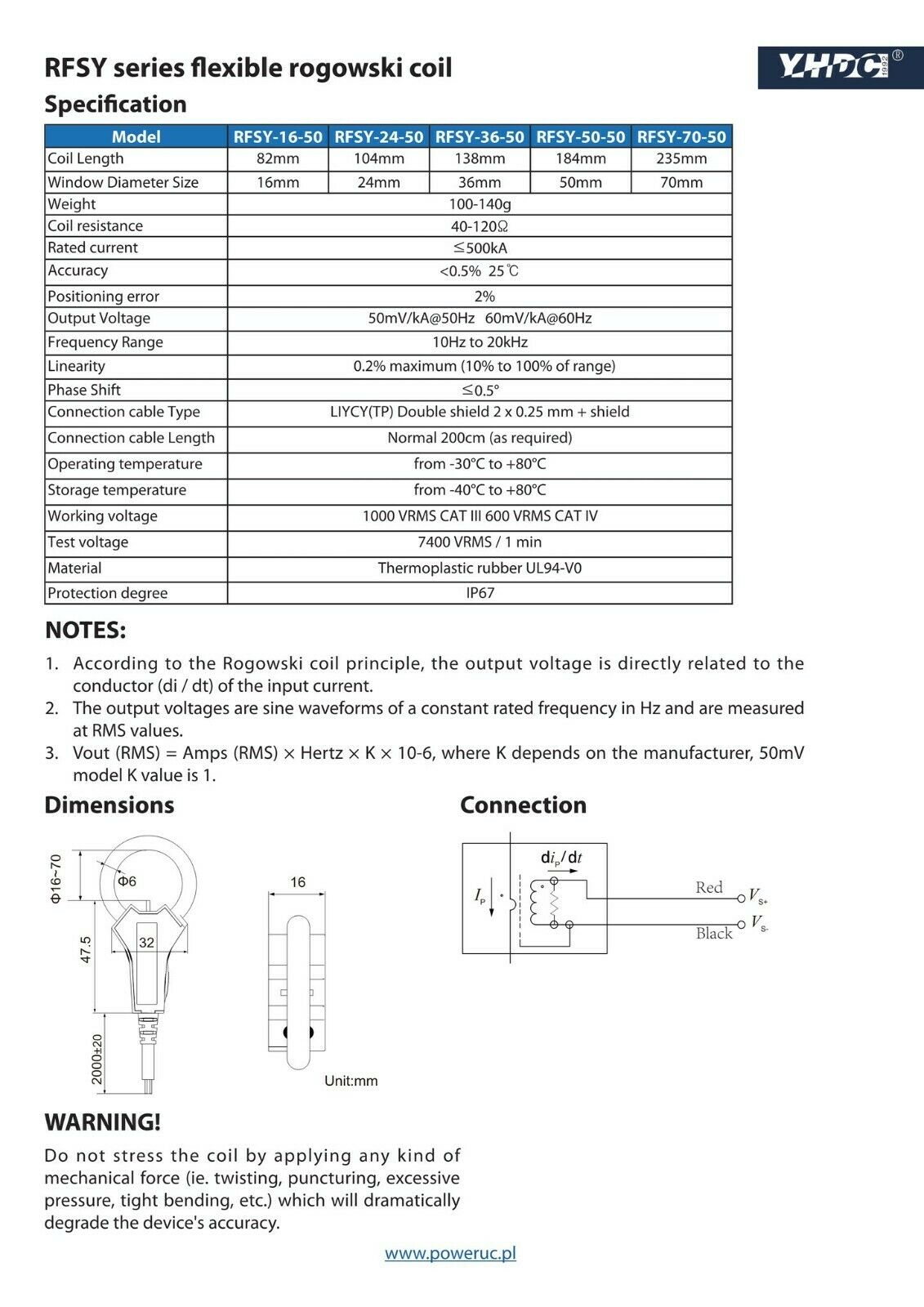
I don’t know what would be involved. You are showing the rogowski coil, I think it may also need an integrator. IoTaWatt accepts a 0-50mA input, or you could possibly connect it to the 13 & 14 VT inputs which accept about 0-15V AC. Show me the datasheet that produces one of those signals and I’ll look into it.
Integrator is linked above also. for some reason, it didnt popup like the first, in anycase,
i copied the datasheet posted and i will put here.
i cant believe i’m the only one with this panel issue…
Thank You!
Thanks, I’ll look into that, but probably not anything that will be available soon, if at all.