Is there a way to use solid core CT’s even smaller than ECOL09 while maintaining measurement accuracy and easy of obtain?
In fact, I have a small electrical enclosure and some cables are small section (14 AWG)
Patrice
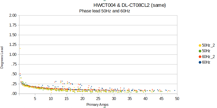
Id recommend HWCT004 or DL CT08CL2 (I believe they are different brands of the same source). You can find them on Ebay or Ali. They will require cords and jacks. The accuracy is good.
Thanks, I’ll try to get and adapt them with jack
Would you have any information on how those are to be wired with the 3.5mm jack?
thanks
Two conductors connect to tip and sleeve.
so there’s no polarity to worry about?
If the two leads coming out of the CT are different colors, it would be good to always lead the same colors to the tip and sleeve, but some of these don’t even have different colored leads. At the end of the day, IoTaWatt will auto reverse them in single phase applications, and you can physically or logically (“reverse” checkbox) reverse them. It could be a PIA to figure out arbitrary orientation in a derived reference three-phase. That’s where being consistent is helpful.
Thanks for your answer.
I will already have 6 CT purchased from you; and I’ll be using those in a 3 phases setup. So being consistent appears important.
I guess I will figure out pretty quickly 
Hello All.
Do you think that YHDC TA17L
(Through core type precision current transformer TA17L Rated input 0-10 – PowerUC) would work similar to HWCT004/DL-CT08CL2?
BTW.
Closed core is a plus for me (smaller space required).
The list from Current Transformers – PowerUC seems quite extensive.
If anyone would have some free time to browse the list and try to identify valuable models for monitoring 20A circuits - I would be obliged.
I found YHDC TA17L to be interesting so far but there are some other (like TA8348S-250) I do not have enough experience to judge.
You have to look at the CT output and the burden. IoTaWatt has a 20Ω burden and expects a 0-50mA CT output. So the input ADC range is 0-1V RMS (20 x .050). At the end of the day, your CT plus burden must be equal to that or at least not so much less as to reduce resolution.
The TA17L-03 has a rated output of 10mA at 10A primary (1000 turns).
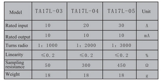
If you feed that into IoTaWatt’s 20Ω burden you get 200mV RMS into the ADC, which is 1/5 of it’s normal resolution. If you were to change the IoTaWatt burden resistor to 50Ω as specified in the table (Sampling Resistance), you would get an output of 500mV. That’s half of the capacity and not too bad but involves modifying the IoTaWatt and depends on your experience, tools and skill level with SMT PCBs.
That covers the amplitude part of the problem, but does not address the phase-shift of the CT. These little CTs can have quite a bit when pushed through higher burden resistors. IoTaWatt can correct shift pretty well, but it needs to have a pre-measured shift profile to do that. Then CTs in the tables have been profiled using a special machine that I built a few years ago.
I’d recommend contacting Echun and getting their ECOL09. If you tell them they are for IoTaWatt, they can provide the correct output with the 3.5mm jack.
@overeasy Thank you for the info.
I did some tests.
I connected 5 different CTs to the same line to compare their readings.
Motherboard: diy-v5-hardware with eeprom set to v5.
SCT-013-000
SCT-006-000
TA17L-03
TA17L-04
TA17L-05
Not changed the burden resistor (it is 20 Ohm).
Soldered TVS to TA17L, and SCT already had TVS.
SCT setup by selecting from the “Model” list.
TA17L configured as “Model” [generic] with “Phase lead” = 0 and “Turns” = according to the manufacturer’s specification.
I connected 2 different devices with a resistive load.
To my surprise, the graphs for TA17L are similar to SCT.
Is this sufficient testing or should it be tested over a longer period of time and with a greater load variety?
Does this mean that I can use TA17L correctly, or is it not very healthy for the meter?
Close-up:
Results look good. For a better comparison, run them all on the same circuit for a few hours, plot the Watts, then click statistics at the bottom and compare the Wh.
As long as it doesn’t exceed 50mA output, no problem.
A simple test I didn’t think about. Thanks for the tip.