So i think i have everything setup correctly now - the only definitive measurements i can rely on are the Grid incoming on the meterboard as they are the correct type of CT.
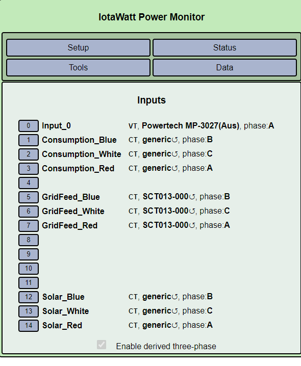
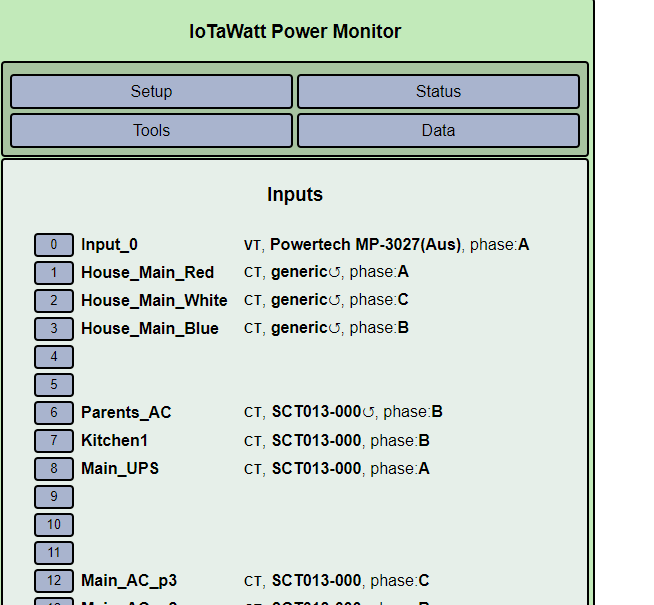
I have run through the 3 phase setup routine as per your blog post recently and have correctly identifed each of the phases and achieved the expected load from a hair dryer. So i think i am good there.
The Solar cables are colour coded as per the previous picture this morning and i have traced them and made sure they go into the appropriate mains cables so i believe i have everything right there.
However the maths is not adding up still
I would expect that as per the previous posts this morning that
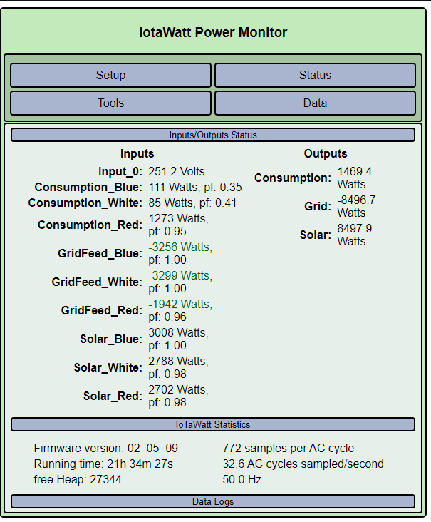
Solar is always + or Zero
Consumption is always + or Zero
Grid can be either + or - depending on the Solar output and consumption.
if you look in the first picture in this post Grid - nearly equals Solar and consumption is not taken into account
The numbers look pretty accurate for everything though - the static house load is about where i expect it to be and where the Electricity company shows it on their daily reports, whilst the Solar is pretty closely matching up with the output from the Inverter - both realtime on the inverter LCD screens and also on the Web portal (which is 6 minute delayed)
It’s clearly wrong. You are exporting more than you are producing on two phases.
This is getting pretty convoluted with the voltage type CTs. I can’t really check out what you are saying about the CTs. I’m trying to understand how you didn’t realize that you had a mix of different CTs and yet coincidentally the three mains ended up with one type, the three solar another and the grid another. You should buy a lottery ticket.
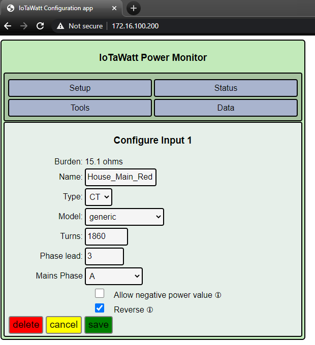
here’s what I recommend you do. Take all of the CTs out and connect the voltage types one at a time to the same conductor as a real SCT013-000. Name it and record the burden setting. Once you verify each one, reinstall and reconfigure.
I saw four black cables in the mains bundle. Are you sure the three that you have clamped are the lines? Is one of those neutral? If not, what is it?
I think you are monitoring the mains on the way out of one setup and on the way into the other. If that’s the case, do they agree?
What do you mean by “static house load”? What do you mean by “pretty closely matching”? When you get this right, it should be within 1%. Is that what you are seeing for daily output?
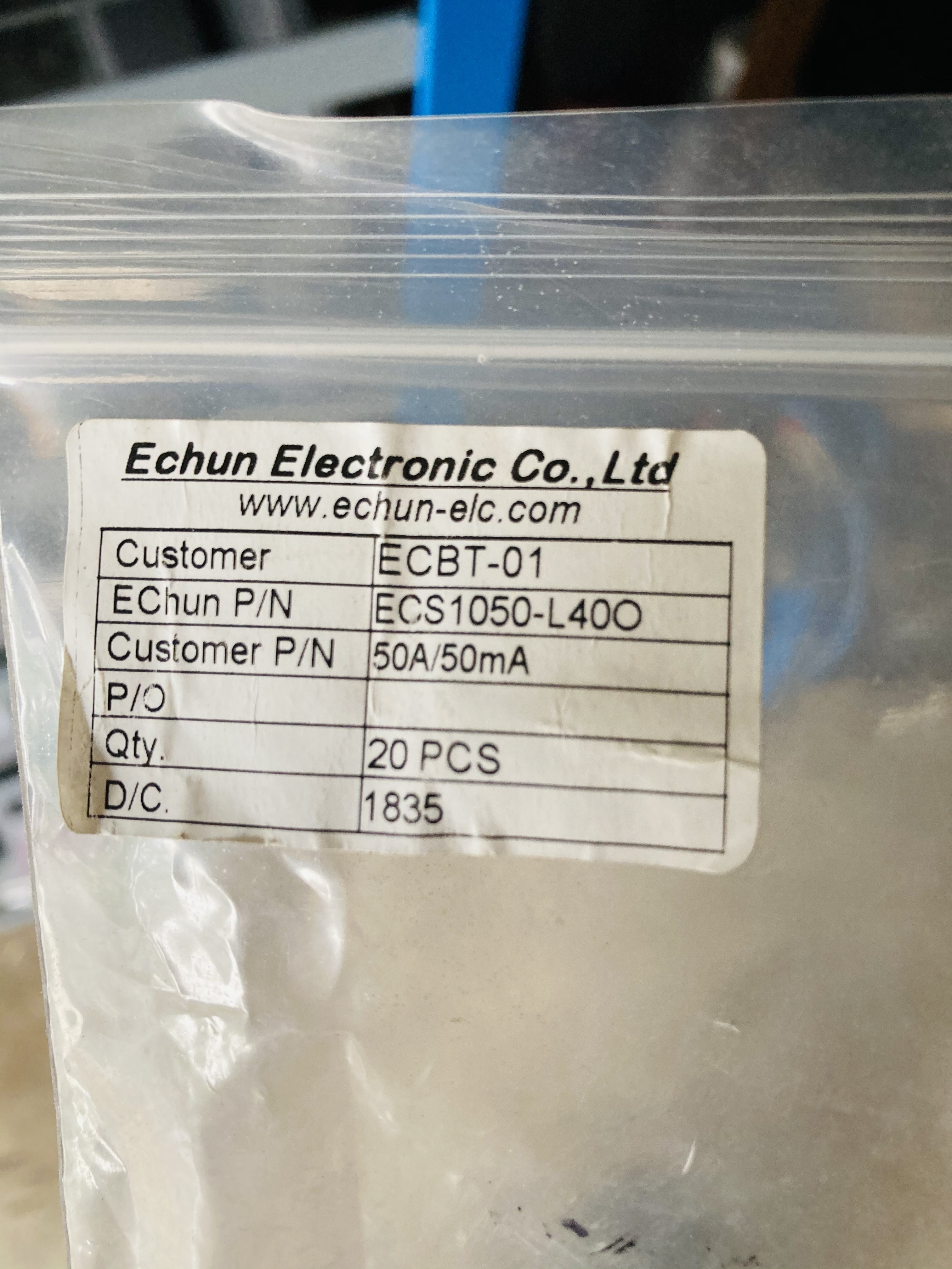
What has happened with the SCT013s is that when i got my first IOTA i purchased 9 CTs from Aliexpress.
3 x 100amp to monitor the main feed into the switchboard, 3 x 50amps and 3 x 30amps
Little did i know the difference between them until now.
So the 100 amp correct ones have always been connected to the mains - initially on my switchboard and now when the main meterboard has just been replaced i moved them out to the mains cable out there.
When i knew my meterboard was being replaced i purchased a 2nd IOTA for it and 20 new CTs - a mixture of 50amp and 30amp - reasoning being that i could put them on the different circuits as appropriate. (I thought i read somewhere it was better to have CTs close to the expected load rather than massively overrated ?)
SO i then took the 100amp units from my internal switchboard and moved them onto the mains cable in the new meterboard, then some of the new 50amps and put them onto the feed from the main board into the switchboard
I also used some of the 30amps on the Solar.
When i started to setup the 2nd IOTA and could nto get consistent/meaningful numbers that when i started trying to work out what was going on.
I am going to go out and triple check the mains circuits first now and then work my way through
I have a standalone meter that i can hook the hair dryer to and then hook each of the units onto through my switchboard and will label them all and se if i can get closer.
Will report back - thanks for hanging in there on this one
Craig
Yes there are 4 black cables one of which is the neutral
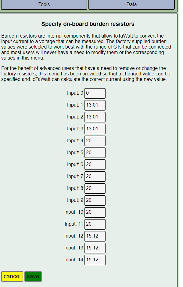
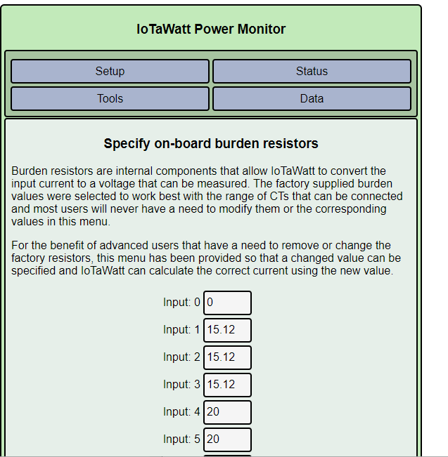
These clamps are all over the place in terms of what burden number to give to get an accurate result.
I hooked a hair dryer up to a kilawatt meter through a butchered extension lead - then worked my way through the first 10 clamps - the numbers were all over the place - so i noted each one down on the clamp itself and then went back to the main meterboard and put in the clamps one at a time with and adjusted the burden values as i went.
I think we have accurate numbers now - still got another 10 clamps to measure and configure tomorrow but i think i am on the way now !!
Craig… where are you located… I will need to check but may have some CTs for you left over from my install. I used 2 iota watts to monitor my 3 phase + single phase + consumption etc over 2 boards. (sydney / blue mountains). Works a treat
Hey Mate, i am over near Chatswood - so a fair hike, if you have any though would be happy to buy them off you ? I will be up in the Blue Mountains (Springwood) - early in the New Year