Bob,
I have two IOTAwatt now and have just had my main meterboard replaced today so am putting everything together into what seems sensible to me (wanted to check with you)
Essentially the main meterboard outside has the grid feed coming into it (3 phase)
The 3 phase solar inverters (two of them) feeding into it
The sub board where all the house circuits are connected runs out of this board.
So the plan is to place 1 x IOTAWATT with 9 clamps in the main meterboard and a 2nd iotawatt with 14 clamps into the sub board where all the circuits run from
My question is - for my 3 phase solar - i have used a single CT on the pair (from 2 inverters) inputs for each phase - so essentially i have 3 clamps monitoring 6 inputs (2 groups of 3 phases)
As it is solar and is input and the inverters balance up the amps output on each channel - do i need/care about actually finding the correct phases and matching them to the grid inputs ? (I am using a single VT and derived for the other 2 phases)
If it do care - how would i go about identifying the solar phases ?? (without needing to get an electrician back ?)
Craig
Assuming that you have the mains configured correctly, and the solar feeds in downstream of the mains, you can switch off the house load and the solar CTs should read the same as the corresponding mains. The inverters should also be very high power factor, if not unity (1.00). Try different phase assignment for each of the inverter legs until it is high-power factor and matches the main with the same phase assignment.
OK will do and report back
Craig
Yep that did the trick - we now have Solar being monitored by my 2nd IOTAWatt
But it has shown me something else a little strange
The background
Originally purchased a single IOTAWatt and installed it on my main switchboard which is where all the circuits fan out from - but is seperate from where the meters and the grid connection comes in.
This switchboard is linked to the main meterboard with 3 phase (Aus) 3 wires. (Red, Blue and White as per colouring in the switchboard
When i configured this up originally i had 3 monitors on the incoming feeds to the board so i could see the total house consumption - but due to the distance to the main meterboard did not monitor grid consumption or solar output.
So i now have my 2nd IOTAWatt which i have installed in our newly installed Main meterboard.
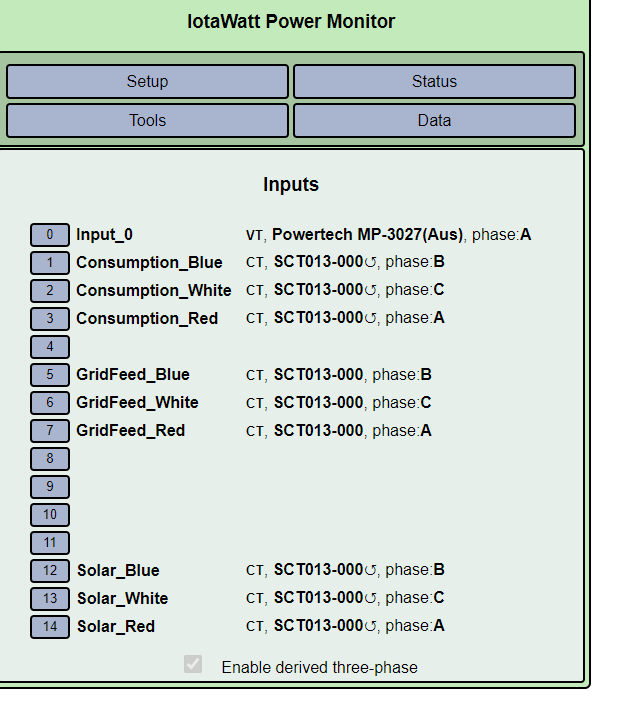
This has 9 clamps - 3 phase Grid incoming, 3 phase solar input (two inverters and used a single CT on each of the phases - so grouped both inverters), 3 CTs on the Consumption side of the meter
So the theory says that i am monitoring (temporarily) each end of the consumption link (essentially the outgoing from the main meterboard and the incoming on the switchboard)
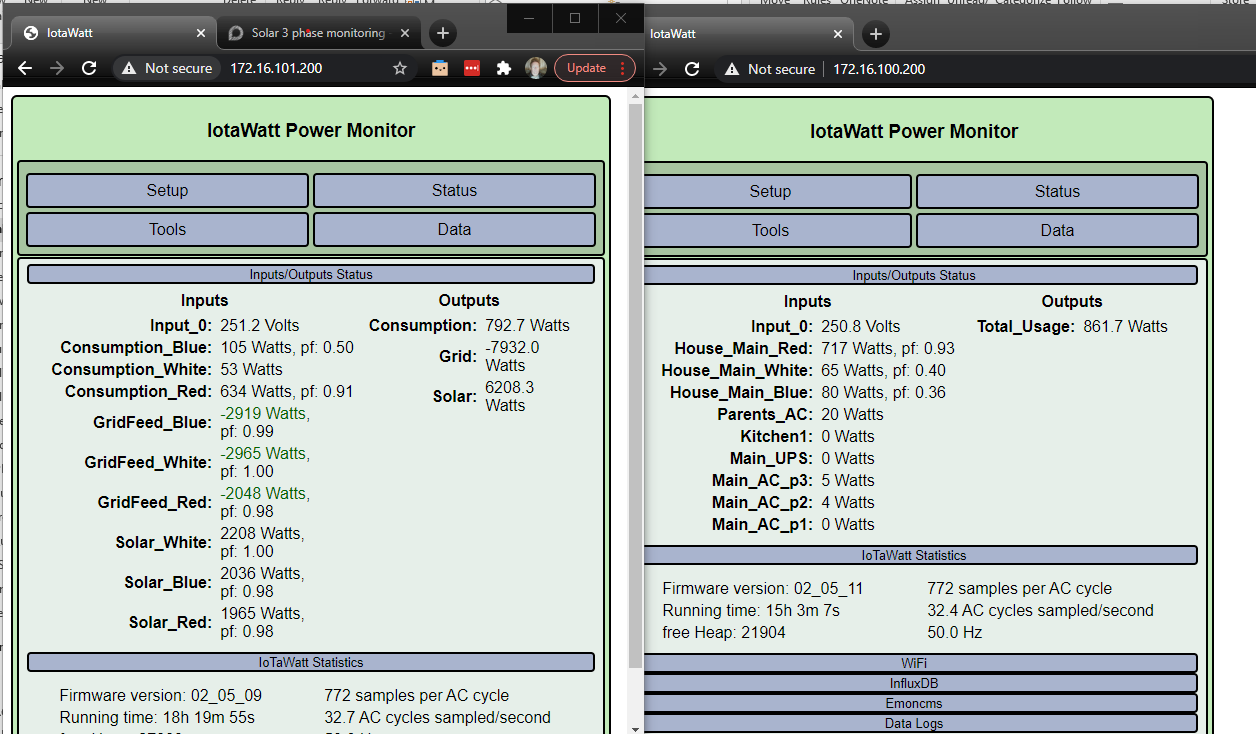
I am however seeing a difference in the two IOTAwatt outputs.see the picture below
They both use the same model of VT plugged into the same phase - and based on your recent blog post re calibrating for 3phase i have triple checked that i have these correct
Any ideas ?
(Consumption on the left is the same as Total_Usage on the right)
Do you tihink i might have a problem with the setup of the IOTAWATT on the left ?
It is showing me putting more out to the grid and consumption than i am producing from Solar - seems unlikely. ?
Yes. If I understand your setup, grid + solar - consumption should be zero. That should be true for the individual Red, White and Blue phases and the overall total. The solar looks right with PF=.99. The others not so much. You may also have a calibration issue either by misconfigured CTs or an installation issue. Can you show the inputs configuration and a picture of the panel?
Bob,
Not quite - We can export Solar to the grid (i.e. produce more than we can consume) so more
Solar - Consumption = Grid (which can be + or -)
I think you are right about misconfiguration - let me start again and come back with some pictures
Craig
It appears your grid is positive when importing power and negative when exporting, so notwithstanding grid can have a + or - value, I would maintain:
Solar - Consumption = - Grid
or
Solar + Grid = Consumption
or
Solar + Grid - Consumption = 0
Just evaluate each of these with Solar = zero.
Bob,
OK here we go
- Input definitions for IOTA at the switchboard - currently only 3 clamps attached, inputs named visually as per colour coding of board - verified as correct. Used the procedure you recently linked to in your blog to identify and setup each phase - the numbers look inline with what i have come to recognize over the last couple of months whilst this unit has been in place
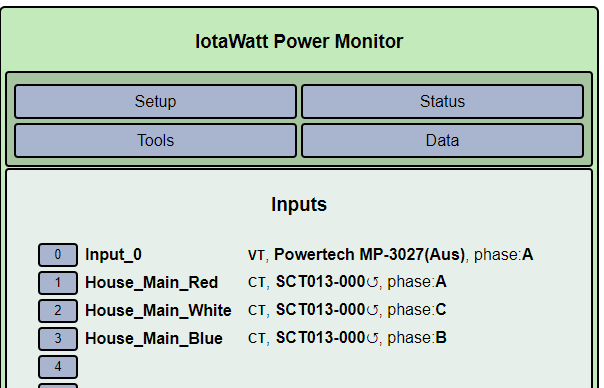
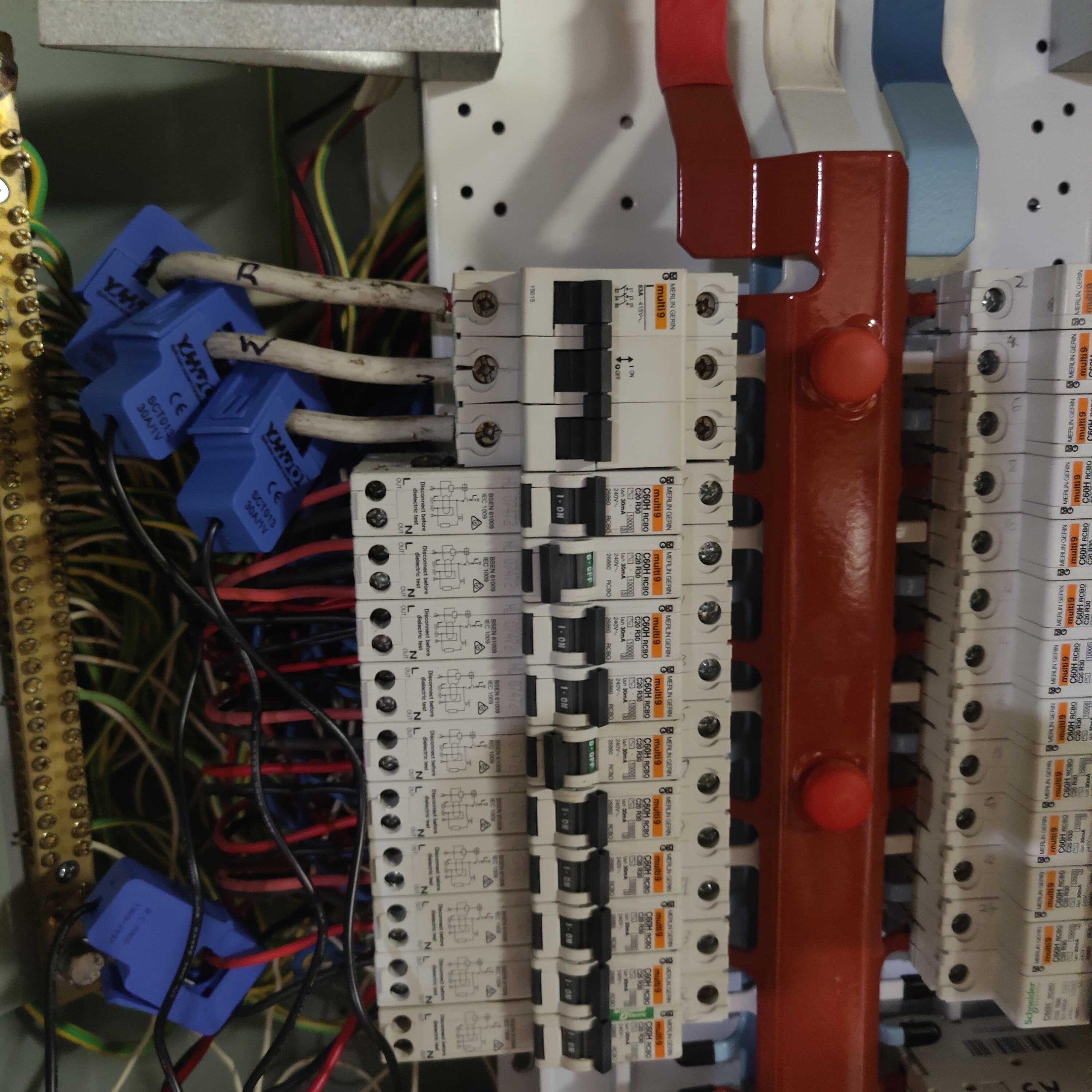
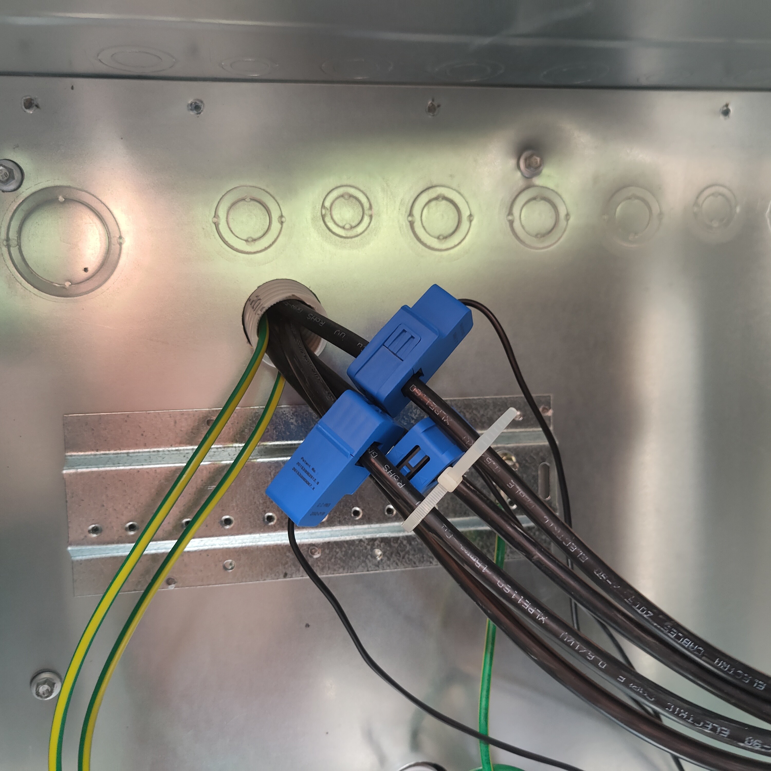
Picture of the board where this is attached to
Another post with the other board shortly
Craig
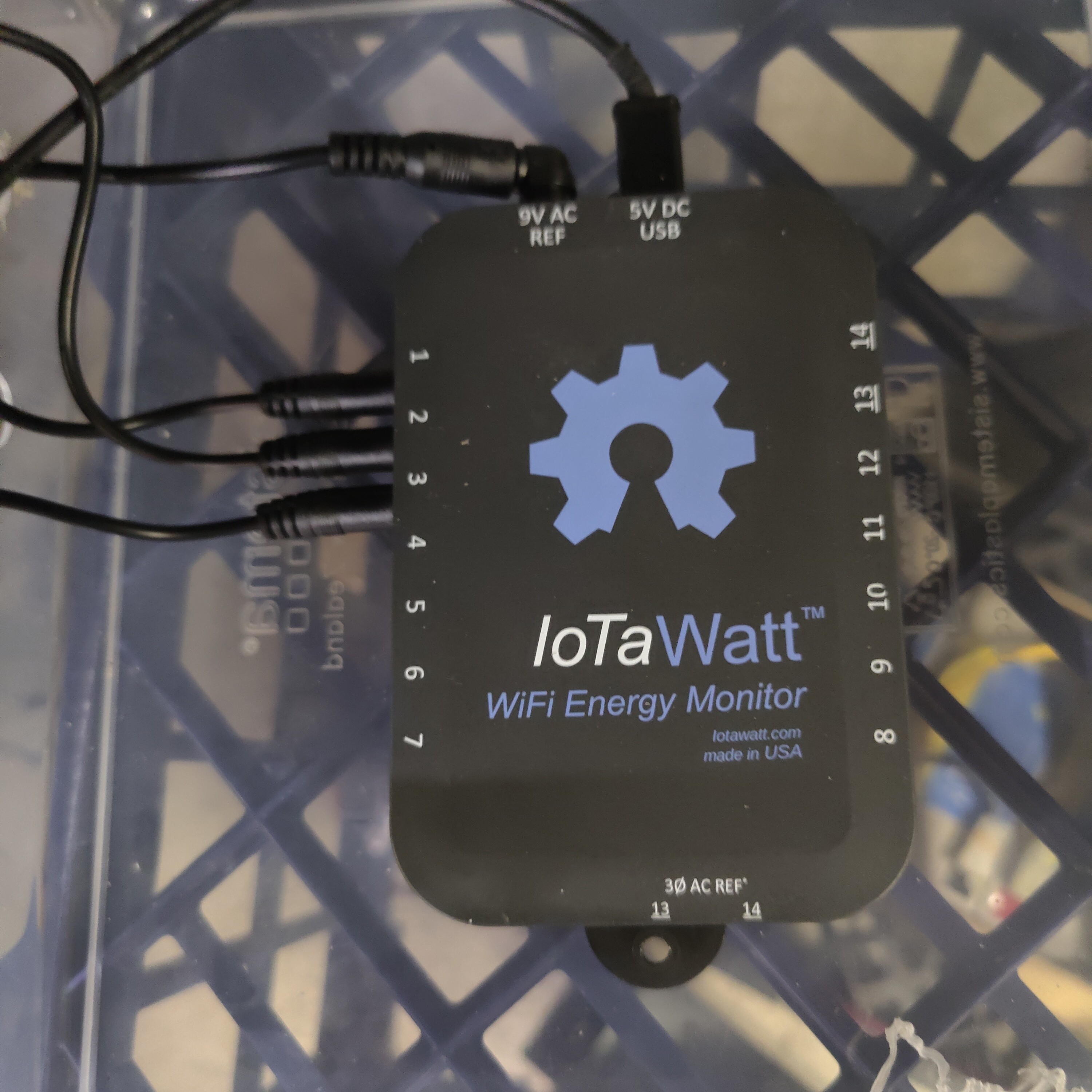
And here is the other IOTA which is connected to the main meterboard
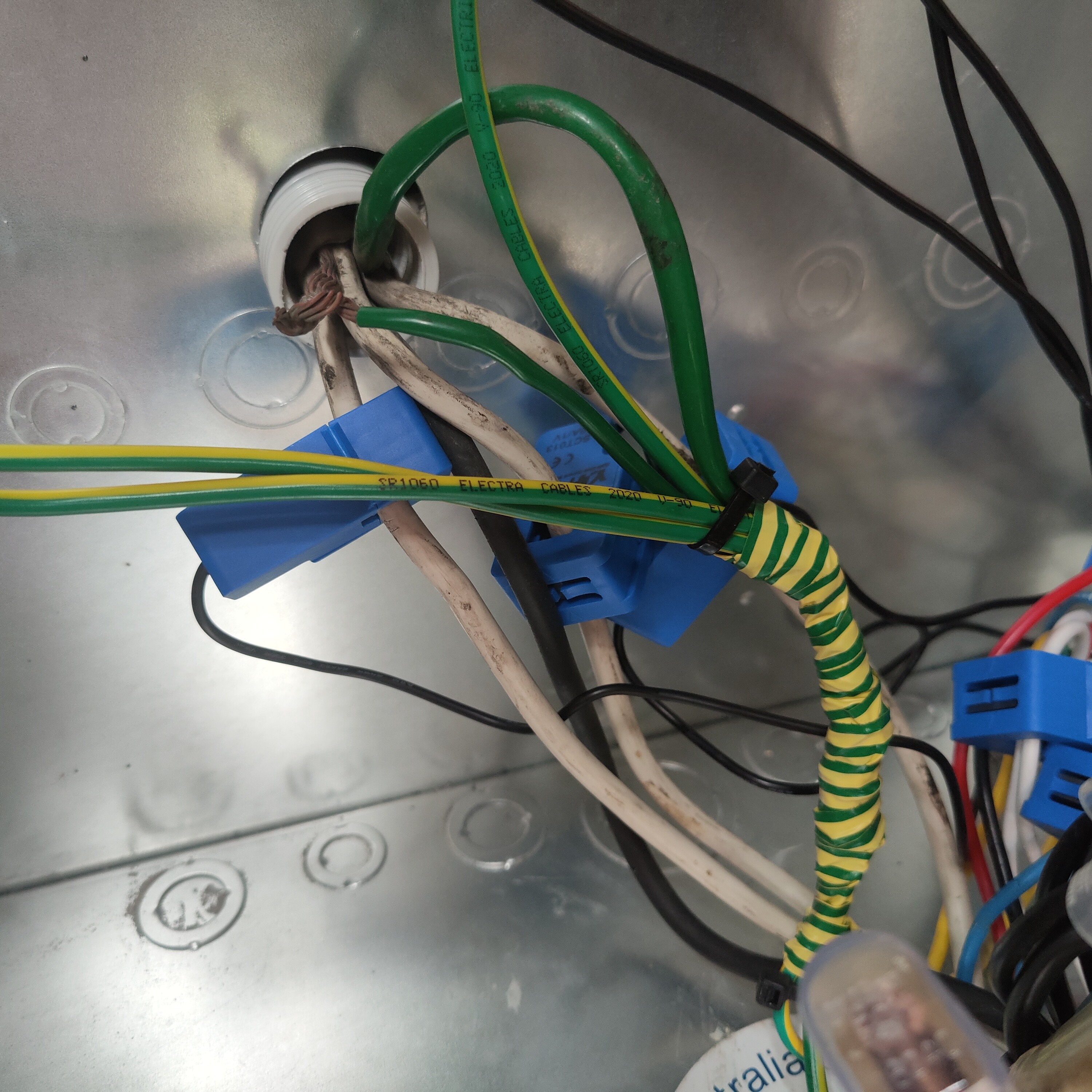
And then pictures of the inside of the board - hard to follow the connections
- Mains coming in from Street prior to them hitting the meter in the board
- COnsumption leads after the meter that feed back to the Switchboard where the other IOTA is
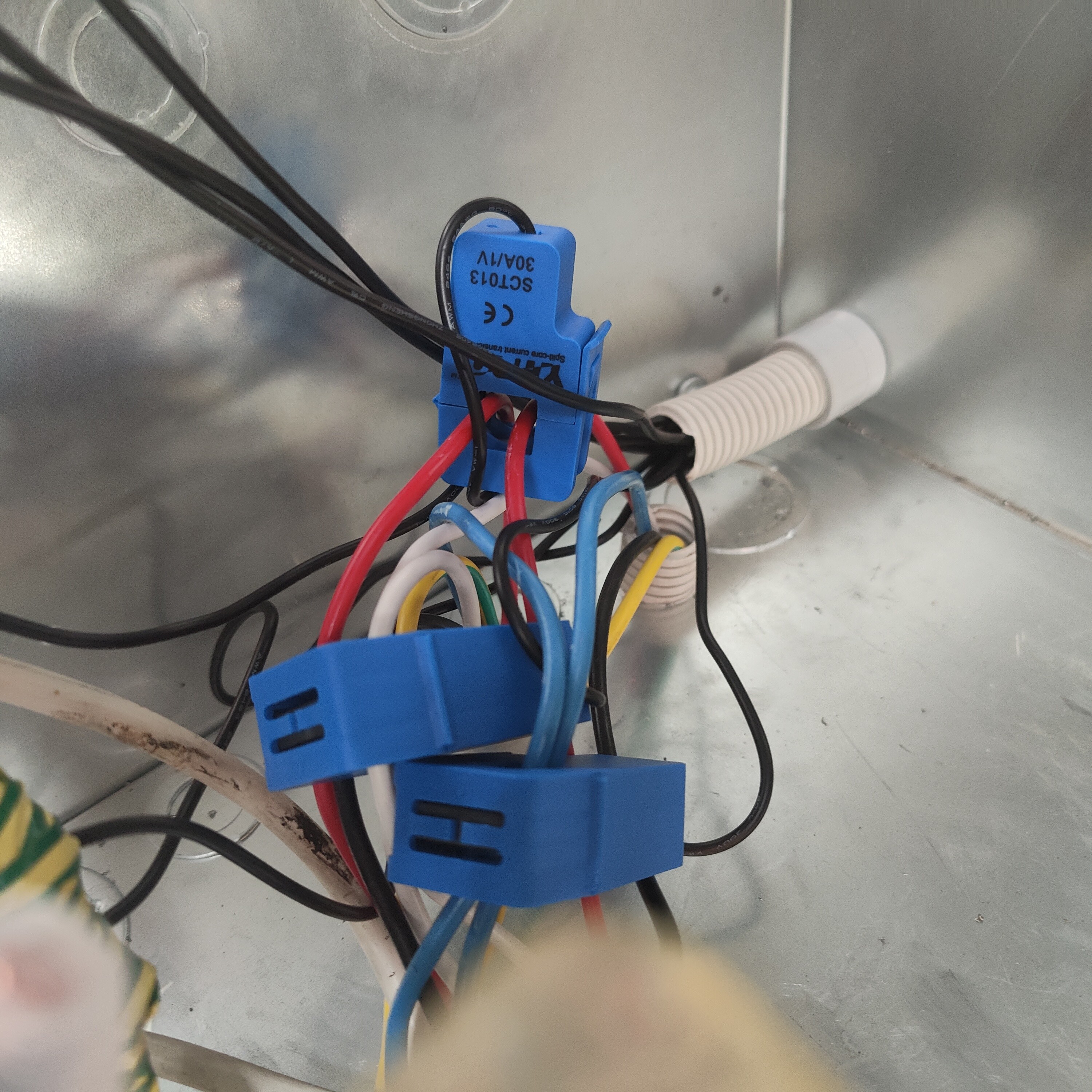
- Solar incoming
I just noticed on the photo of the Solar feed in - the CTs are 30a/1 volt - is this what IOTA expects ? as my solar read seems to be way lower than i would expect) and that i am seeing from my vendor supplied app
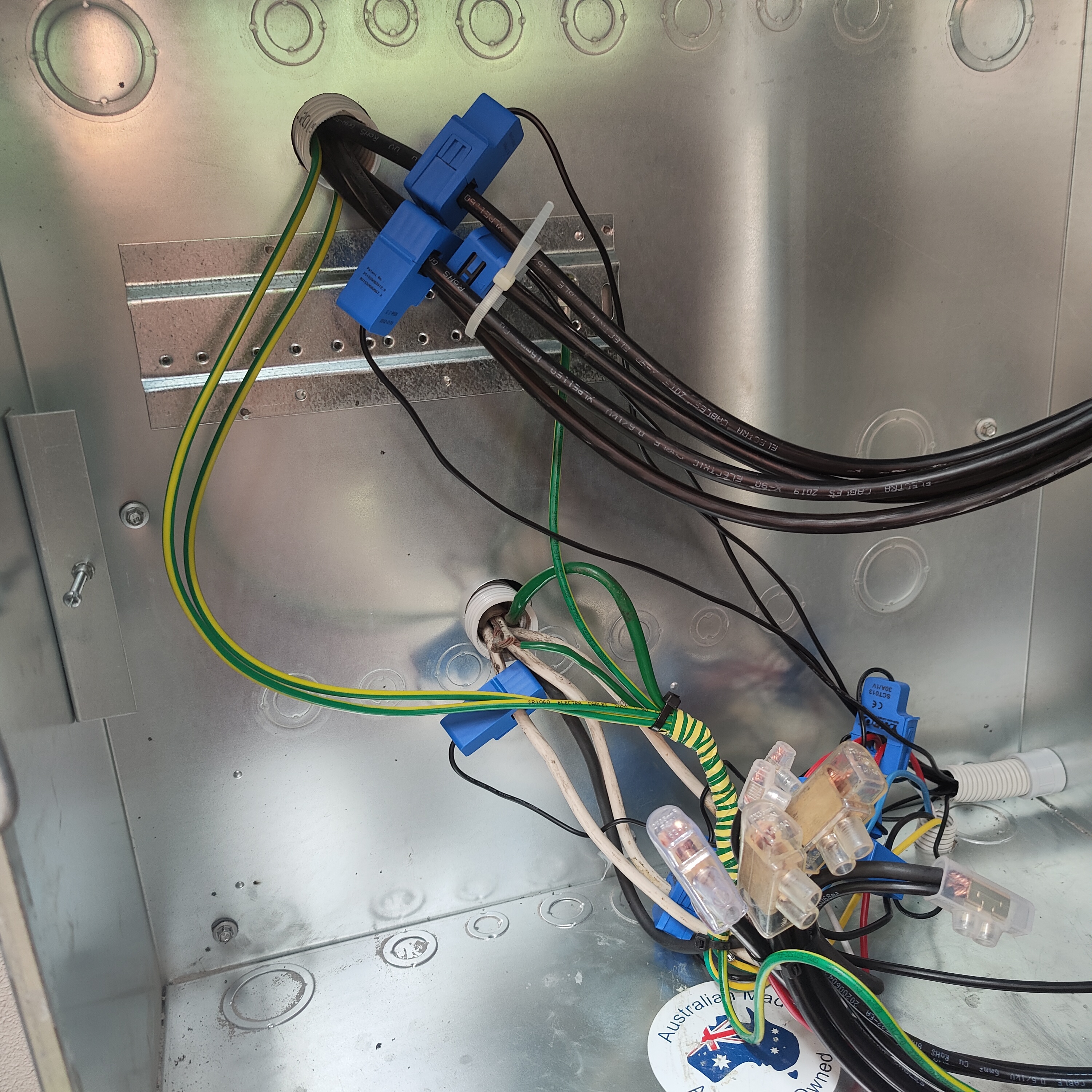
The whole lot in one photo
Craig
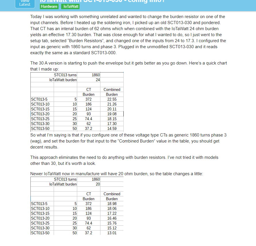
So just reading through more of the doco - would i need to change the burden from the default of 20 to 30 for a CT that rates itself as 30/1v ? (as in the picture ?)
I have just done this for the solar feed ins but can see no discernable difference
Craig
No, it isn’t. Those are voltage type output and will read about 25% lower (V5). They can be made to work but I don’t recommend using them. While you could get them calibrated, they will not have the resolution of a 50mA CT the unit was designed for, and those YHDC have a lot of phase shift even with the supported SCT013-000 model. Shift is greater and not calibrated in the voltage varieties.
OK i have a problem then as i have just looked at all of the YHDC i have purchased and they all output voltages not amps.
So i currently have 24 of them of various sizes which i will need to stick with for the time being.
Can you link me to the procedure to get them as accurate as possible ?
Craig
How handy are you? The best way to proceed is to do a burdenectomy on them to convert them to current type.
Reasonably handy i think - do you mean to open them up and remove the burden resistor ?
Point me to somewhere with some pics and i will give it a go !
Craig
I have just checked all my CTs and the only ones that do current are the 100amp units on the mains - so i have orientated them the correct way now and they show up correctly now ( i believe)
Craig
OK this looks like a start if you can confirm that i am just removing the 2 x burden resistors ?
Craig
Bob,
Sorry to take up so much of your time on this
Have found this post from yourself - will give it a go before i start opening them up and see how accurate i get
WIll report back
Craig
OK for any other Aussies that end up here - this actually works and seems to be very accurate based on what my Solar is telling me - will wait for Bob to confirm but using the 2nd table (link posted below) seems quite accurate.
Note sure if i will gain any more by opening up the CTs - Bob can chime in when he wakes up later tonight !!
Here is the post on OpenEnergy
And here is a post about opening up the unit
https://owenduffy.net/blog/?p=11205
Craig
What, it’s 9pm? I’m good till midnight.
I’d like to see your status when you think it’s settled. Hopefully, everything will add up.