My panel upstairs is made up of the following inputs:
- UpMain_1
- UpMain_2
- Barn_1
- Solar
Barn_1 and Solar are setup as x2.
I’ve included a link to the pictures I’ll refer to below.
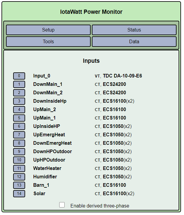
- Inputs - inputs screen to show how they are setup
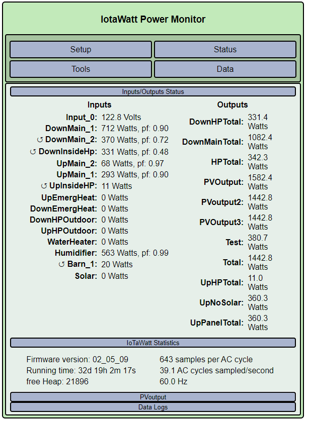
- WithOutSolar - input values when I turn off solar
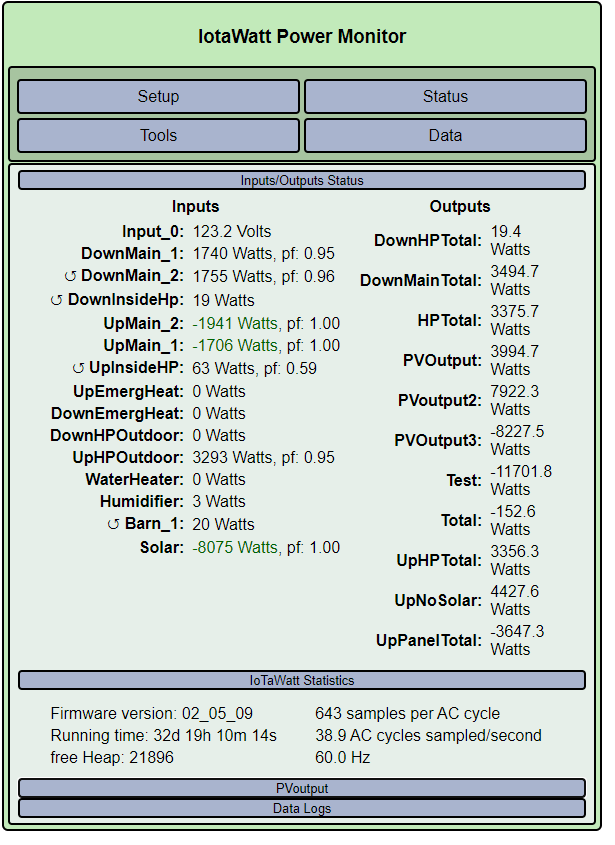
- WithSolar - input values when I turn solar back on.
The issue: When I have solar off, my upstairs panel shows a consumption of 400-500watts. This is pretty steady 20h per day as it is just my computers, and refrigerators. Nothin much on this panel. You can see in picture 2 these values.
When I then turn on solar it is measured by the Solar input and it does match what my inverters say. However it isn’t properly reflected in UpMain_*. There are only the four circuits in this panel that I listed above. So where is the 4k going? Is there something wrong when a sensor goes from + to -?
This error makes it difficult to track my real power usage.
I’ve been looking at this and just can’t figure out what is happening.
any help appreciated. I’ve never tried to share pictures from google to everyone so if my link doesn’t work please let me know.
thanks
david
Picture links didn’t work. Would prefer you just drag-and-drop into your reply. It’s a lot easier than switching browser windows to see the pics.
Do you have another IoTaWatt at the other panel, and if not, are you using extensions on the CTs?
EDIT: Actually the picture link does work. Looking at it now.
Where is the inverter tied into the system?
The inverter is tied into the Solar input. That is measuring one leg of the 40A 240V breaker.
I have a single IotaWatt and am using extensions. The extensions are about 50ft long and are made up of two cat 5 wires.
I have the solar and barn circuits in one cat5 and the UpMain1 and 2 in the second cat5. I wondered if I was getting poor readings because of the extensions, but the solar does match my inverters and the mains do match what I expect. I thought maybe there was a bit of interference, but verified that I have them in two separate cat5 cables.
david
Is that breaker inside your main panel or the upstairs panel?
I have two panels, downstairs and upstairs. They both tie directly into my 400A meter. So they are in parallel to the each other.
Solar is in the upstairs panel.
Can you post pictures please?
What I expected to see is upmain_1 + upmain_2 to track Solar minus whatever power I’m actually using. It seems to be tracking at about 50% of that.
Sorry, I meant pictures of the panels showing the breakers and CTs.
I wondered 
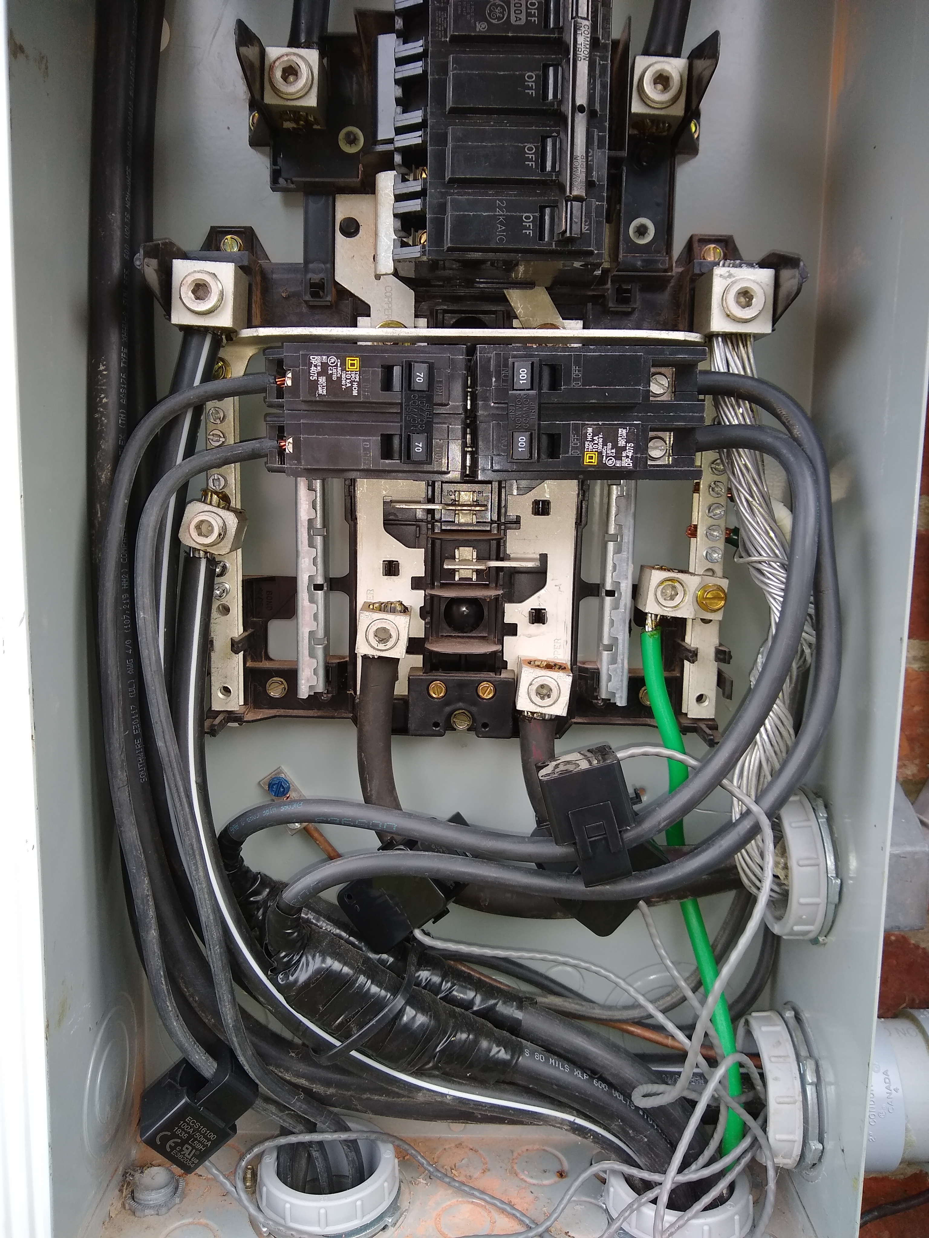
OK . . . they are a mess as I’ve not “finished them” but I’ll get some pictures now.
I did check the voltage and they top panel and bottom panel are close.
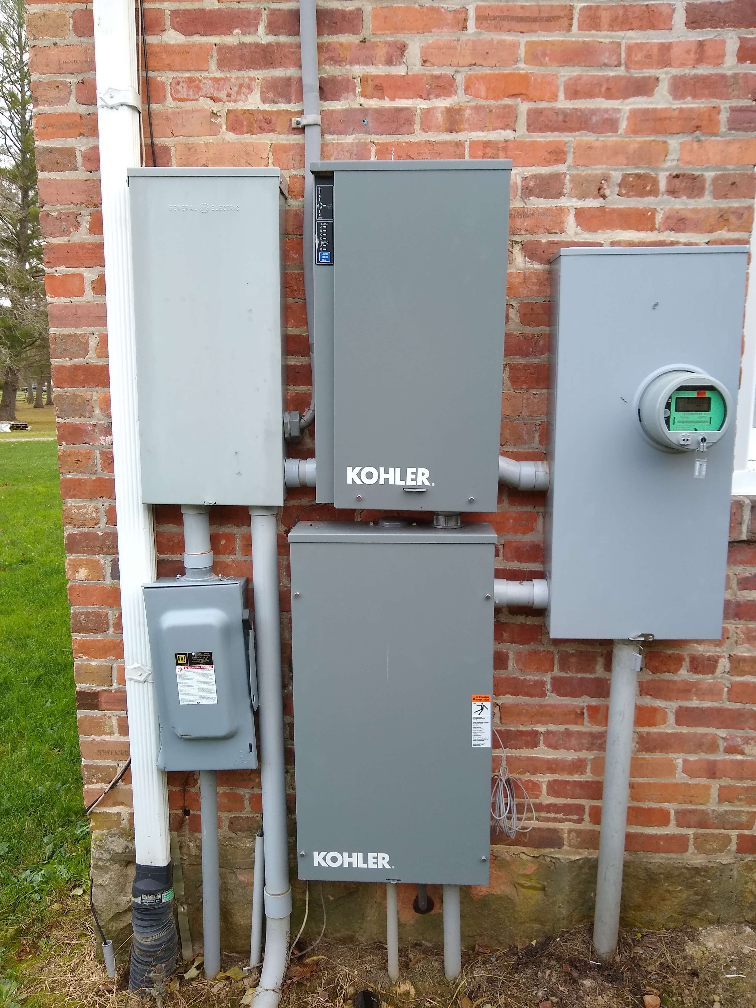
My electrical connection to meter:
This is split with one branch going into the bottom Kohler panel that then feeds downstairs panel.
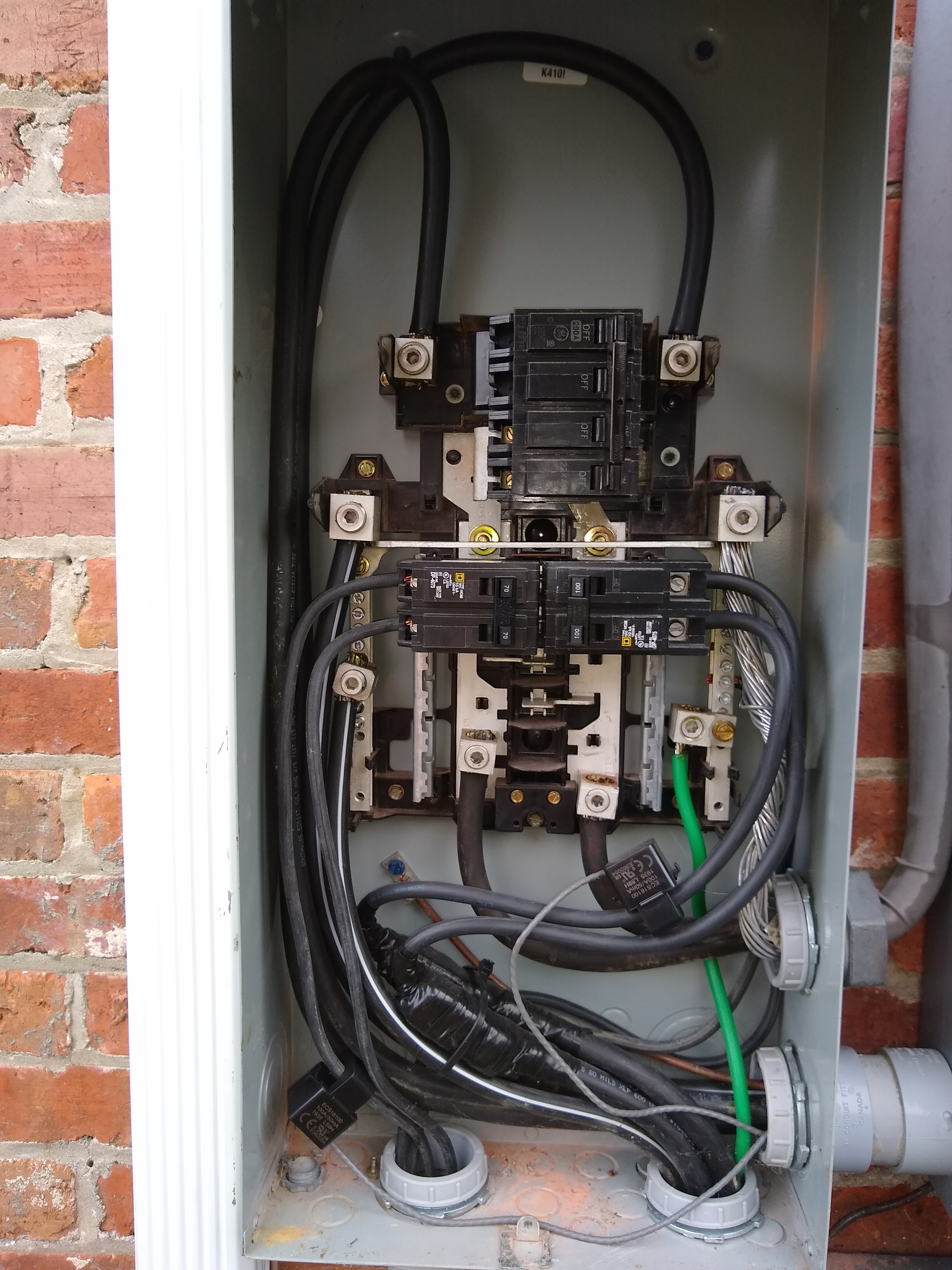
The upper Kohalr panel feeds the subpanel to the left. This is where I tap into the upmain_1 and upmain_2
The subpanel on the left, I connect to Barn and Solar. Barn is the 100A on the right and solar is on the left. You can see the feed to the upstairs panel feeds off the bottom of this sub panel.
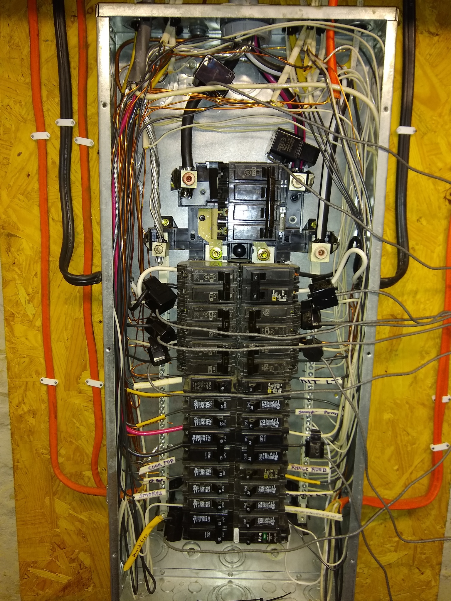
downstairs where most of the monitoring happens
IotaWatt with extension coming from UpMain1_2. you can see the other end of the extension box.
thanks
david
OK I took some voltage measurements.
both upstairs and downstairs are gettin 300V from the meter. Yes 300V not 240V. However my reference voltage stays ~120V. It should be ~150V.
Yes I guess I need to call my power company and see why it is 300VAC, but why is my reference voltage off?
david
I rewired my upmain 1 and 2. to just measure the current going into that panel. Not sure why I didn’t do that to begin with, but it should make my math a bit easier.
Not sure why I get voltage measurements of 300V, that is a bit disconcerting.
If IoTaWatt is saying 120V, then I would suspect your meter. What do you get when you measure the plug where the VT is installed?
In any event, it’s split-phase, so when you measure across the two mains, you should see ~240V, and either phase-to-neutral should be ~120V. I wouldn’t be calling your power company just yet. My sense is that your inverter would be smoking if it’s really 300V.
A picture is worth a thousand words… You didn’t mention the generator. Not that I think it’s the problem (I don’t know) but it is a complicated setup.
First things first. I looked up what you ordered and there were 3 200A CTs and 4 100A CTs. You have 2 200A CTs configured and 5 100A. So I’m thinking one of those 100A is actually a 200A. Can you reconcile that?
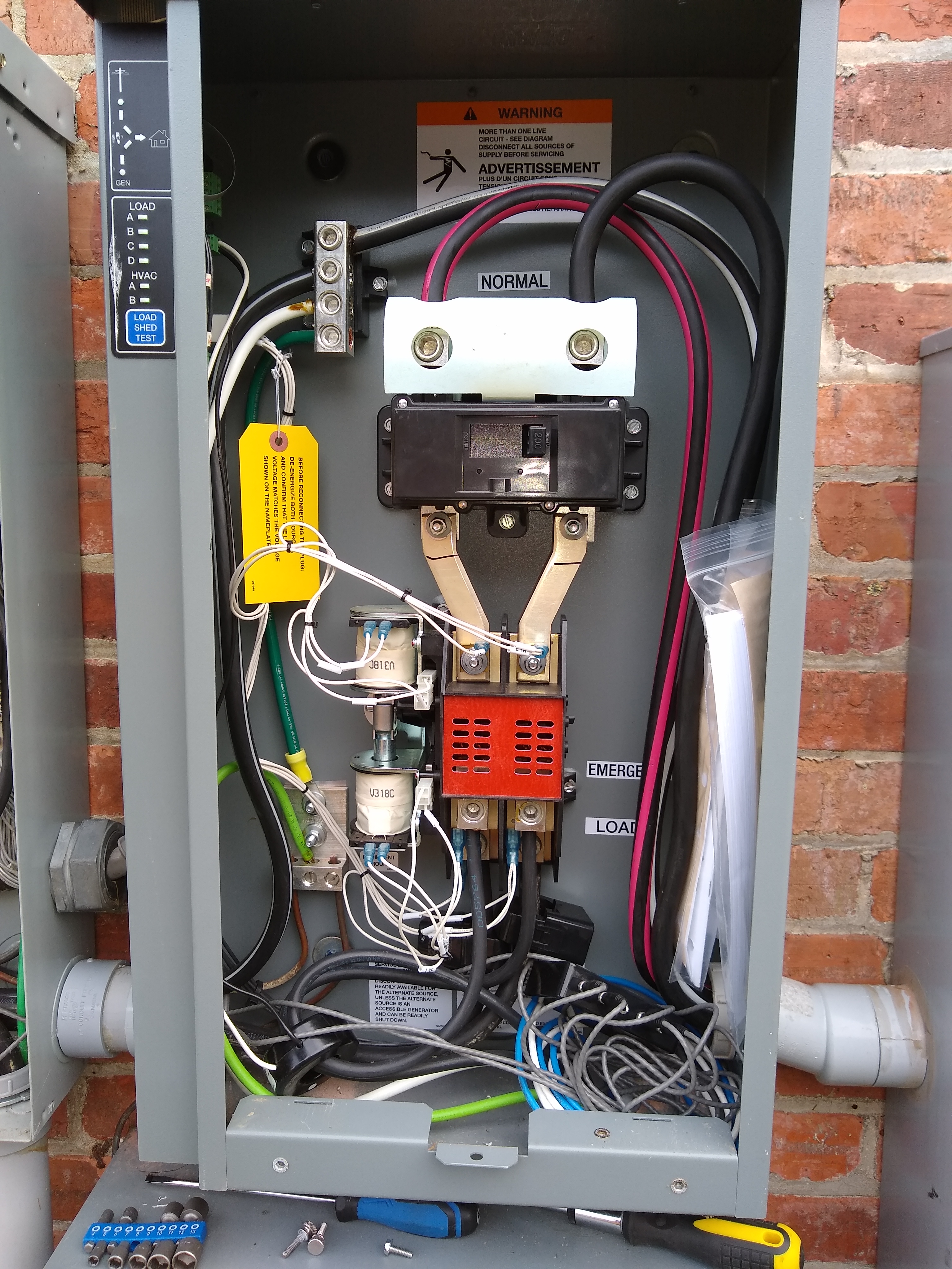
The cables from the transfer switch to the Upmain feeder panel are pretty fat. I see you have a couple of CTs shoehorned into the “load” cables on the transfer switch. If those are ECS16100 I would imagine they are pretty tight. I think you should be using the 24200 CTs for that, but also, I think you could simplify and put the CTs up on the incoming cables where the “normal” label is. It looks like the IoTaWatt is powered by the downstairs panel and wouldn’t work while under generator anyway. Since you want to reconcile with the meter, you don’t want generator power in there anyway.
I’ll take it that the extension box is wired correctly, but just to be sure, that looks like Cat cable. If so, why didn’t you just use the 4 twisted pairs of one. I gotta throw a flag for passing the upmain CTs through the same conduit as the mains cables. It’s not code, but more importantly, that could easily be influencing the CT outputs.
Just picked up your latest post with the moved CTs. That’s a whole different scenario. Now the solar is inserted before the mains and should not effect them at all.
I have to also ask whether Kohler thinks it’s OK to have solar feeding into the mix while the generator is running?
I will double check the CT’s. The two measuring upmain1 and 2 are 24200s, solar and barn are 16100s. I did check those when I took the pictures.
When the generator is on, it activates a solenoid that disconnect the solar AC mains. This causes them to shutdown anytime the generator is running, even when it does its weekly cycle. Yes you cannot back feed power into the generator. I just didn’t take a picture of that as it is on a building next to the inverters and the generator.
I do wonder if the inverters (SolarEdge) could cause the voltage to spike. I have measure wall outlet voltage upstairs and it was ~140V. I thought it an anomaly, but maybe no.
thanks again
Again, I would suspect your meter. The IoTaWatt will be within 1% or so without calibration. Check the voltage at the receptacle and see how it compares. 140V is high, and the 150 implied by the 300V reading would start to damage things I would imagine.
I have read 140 at the outlet. This is an outlet hooked to the uptstairs panel. I’ll ask the electrician that hooked everything up if he remember if the 400A service meter has two connections or one connection.
If one connection I don’t understand how I could have different voltages. I think Kirchhoff’s Laws still works today
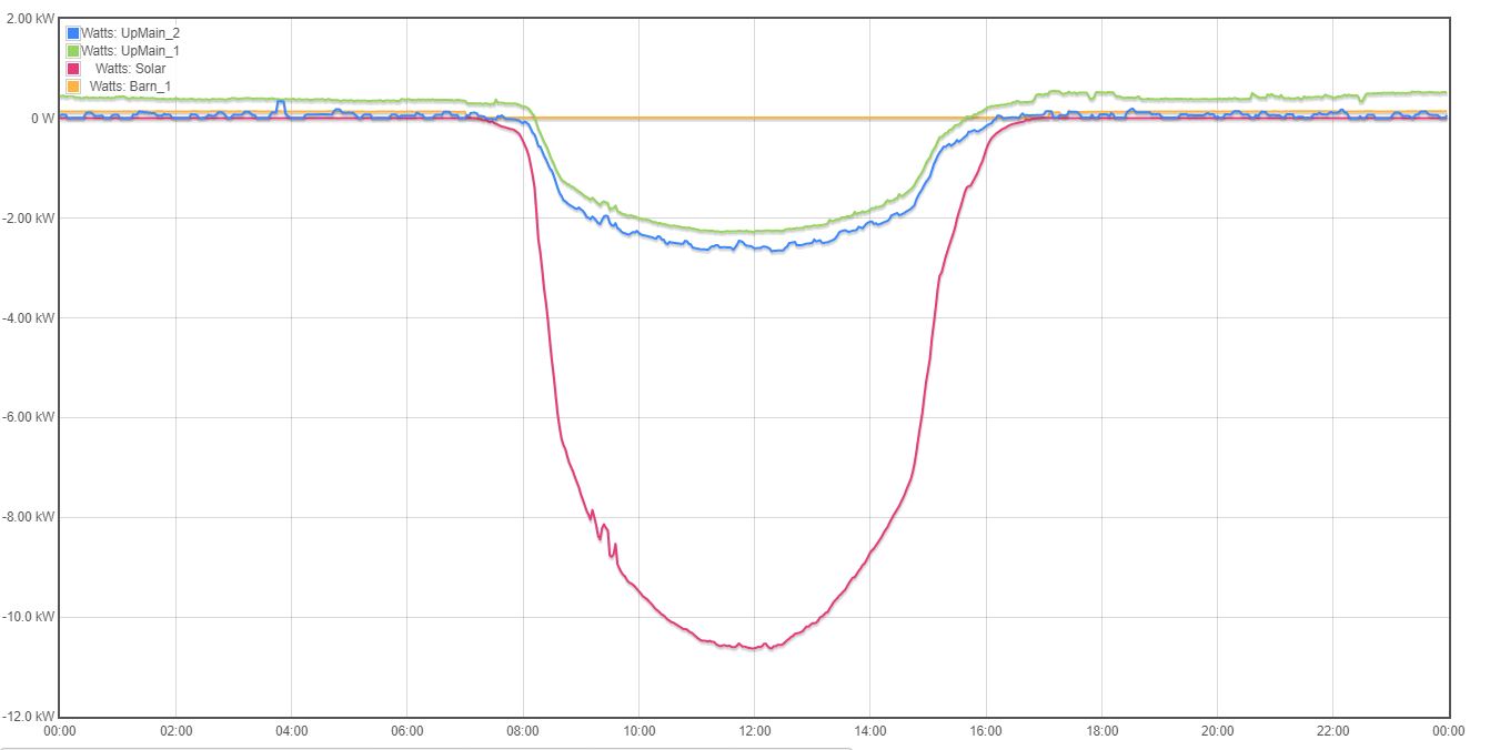
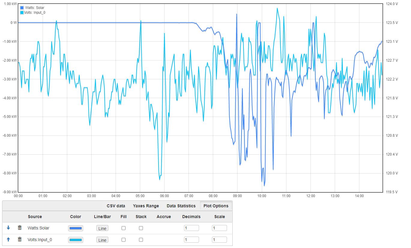
Can you plot voltage and solar Watts for today?
Is it possible to have two reference voltages logged? I do have an unused extension for my upstairs that could could hook up to log both reference voltages. I just know know if Iotta can handle that.
david