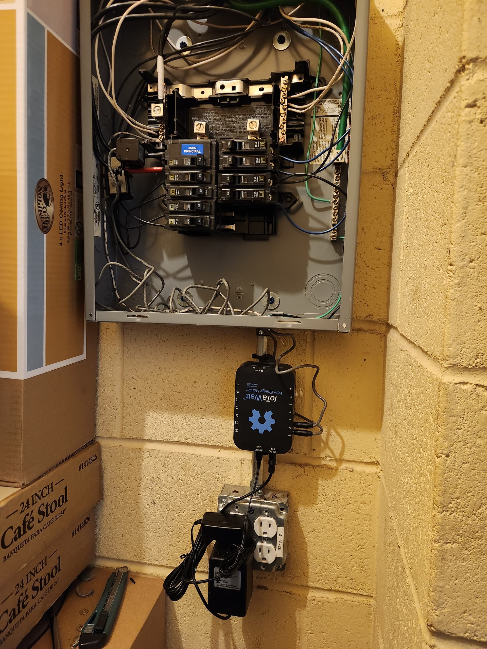
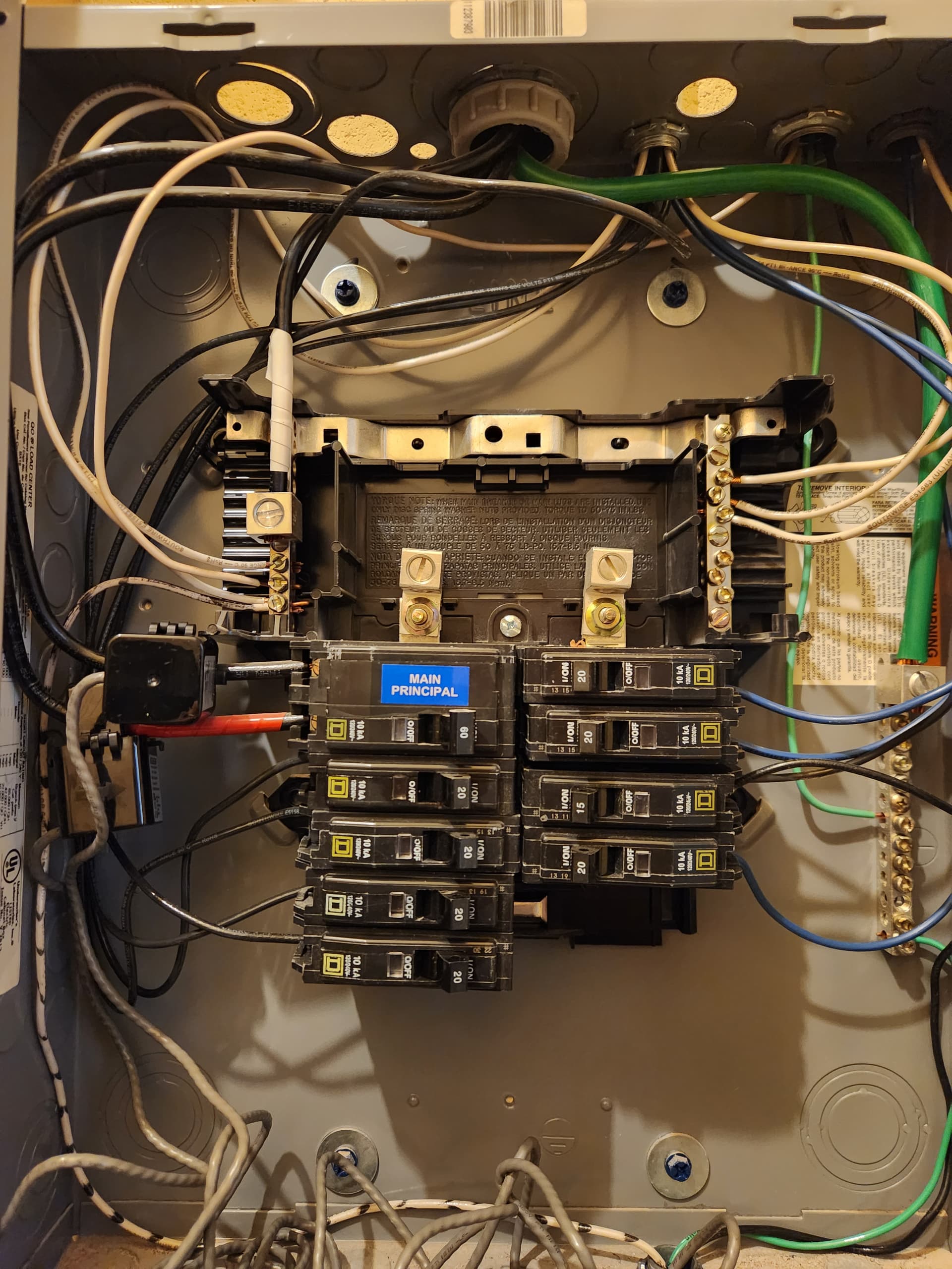
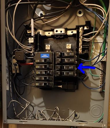
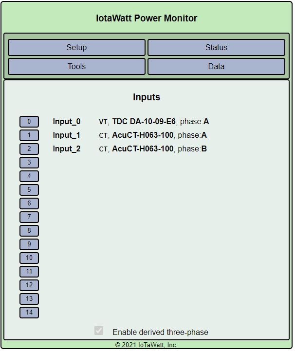
Hi all, I have just installed an Iotawatt and it doesn’t seem to be working properly, I’m assuming I’m doing something wrong. My building has 208v 3 phase power, but the panel I’m monitoring is only single phase, fed by 2 hots, a neutral, and a ground. I have a TDC DA-10-09-E6 connected for my 9v AC reference ground, and a 5v USB DC adapter. For my CT’s, I’m using 2x AcuCT-H063-100, 1 connected to each hot leg. Here are pictures of my panel:
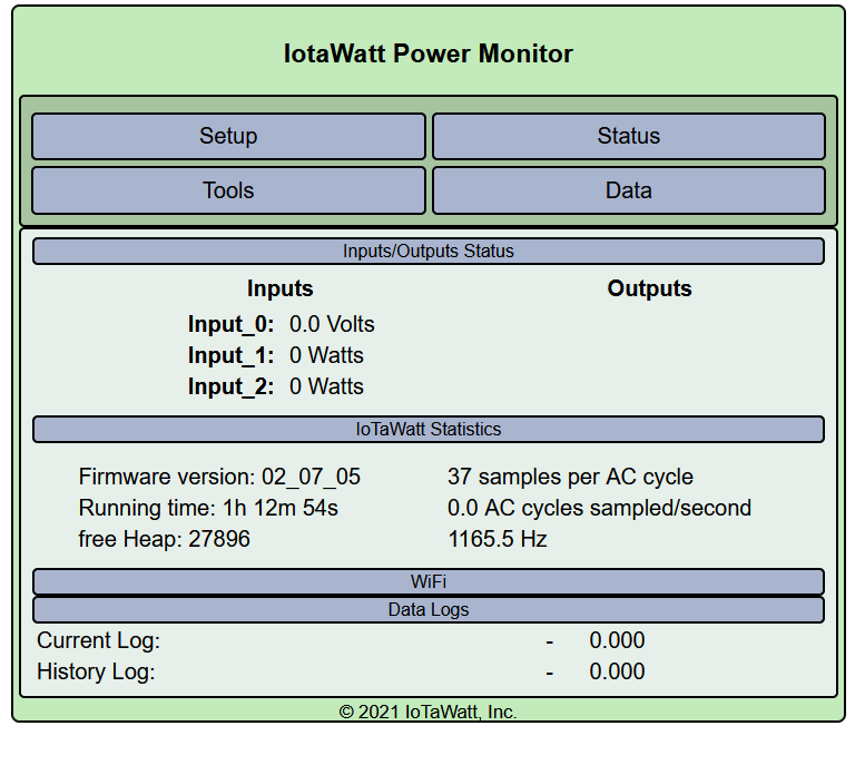
The immediate issue is that the voltage reference isn’t working. You might check if the transformer is putting out any voltage.
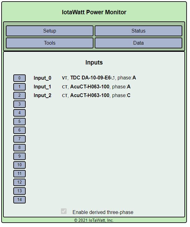
Once you get a voltage reference, you will need to treat your service as three-phase using derived reference. You only have two of the three phases, but that’s ok. You cannot treat it as single or split phase.
Thanks, I just checked and I’m not getting ANY voltage out of that adapter. What’s the warranty on that? I literally just pulled it out of the box yesterday, but I purchased everything a year ago January.
I stand behind things for a year. I’ve never had one of those DOA. If you send it back to me, I’ll send you a replacement part, but I don’t have any of those TDC anymore.
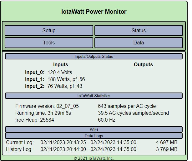
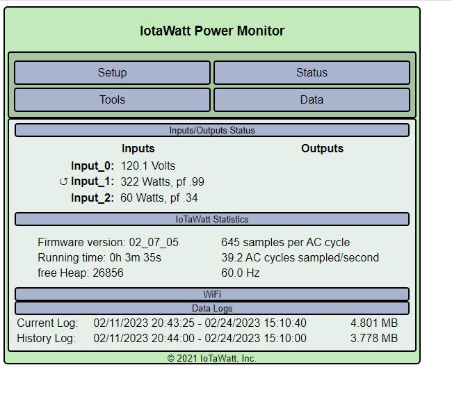
Hello, i received the replacement transformer and am now seeing 60hz, great! Next, I went through the documentation about setting up derived reference. It states to connect CT’s to each of the 3 phases, but in this panel I only have 2 legs. Any hints on how to proceed on that?
You don’t have any 240V loads, so the two are completely independent. Without CTs on the loads and/or some knowledge of what they are powering, I have no idea. They are certainly plausible.
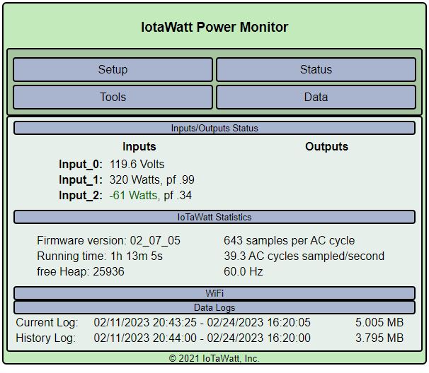
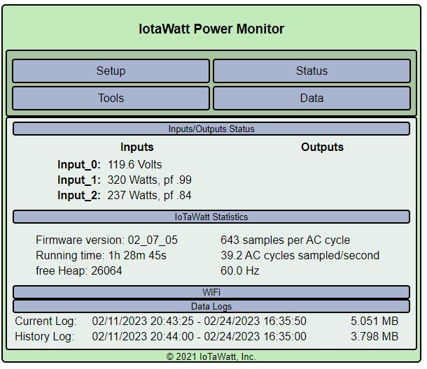
Input_1 seems to have a constant load of about 140Watts and a transient load of about 180Watts.
Input_2 appears to have a constant load of about 90Watts, and transient loads of about 130 Watts and 50 Watts.