Strange reverse current issue

Just taken delivery of my iota watt equipment and started setting up. I’m in the UK and have a split phase 240v supply, so 2 x 240v phases, one for the house and one for the farm outbuildings but both going through the same meter.

I’ve configured 4 CT clamps so far as follows:
1: Phase 1 total
2. Phase 2 total
3. PV generation
4. Heat Pump.

The PV is on phase one so CT clamp one is set to allow negative values for when we’re generating more than we use and so are exporting power.

However, no matter what I do, the reading for CT clamp 1 is always negative. I’ve confirmed that it’s the correct way round. I’ve then attached it to the same cable as clamp 2, and it gives an identical positive reading on the phase 2 cable, so the settings seem to be correct.

I turned on the heat pump and the reading became even larger negative values so it wasn’t a case of just having more generation than the PV clamp was telling me. I’m now trying to figure out if there’s something strange in how the meter wiring is working. I’ve attached some photos below.

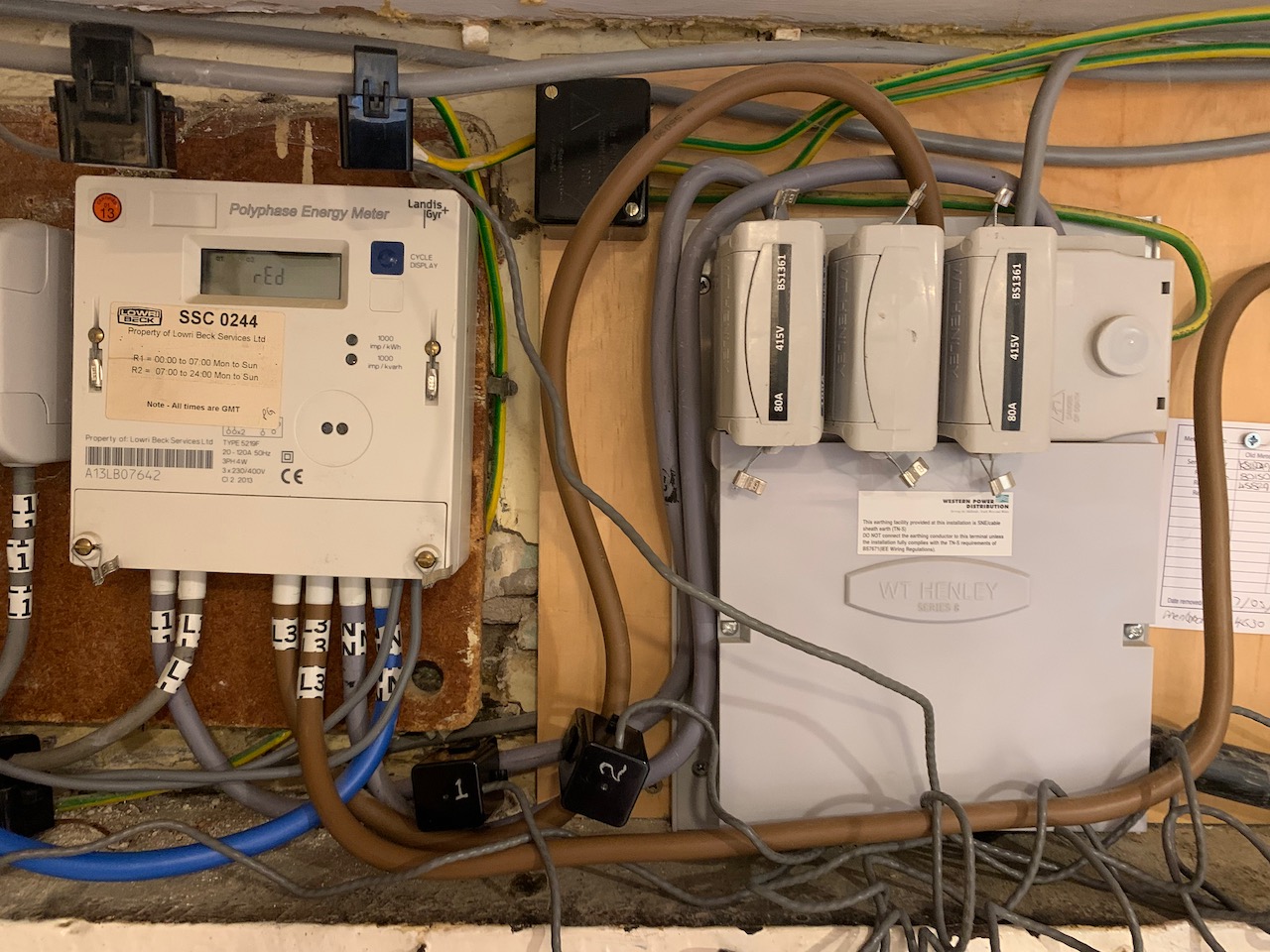
So this is the main tails coming in, you can see Live 1 and Live 3 labelled going in to the meter. Live 1 is the feed that is always negative.

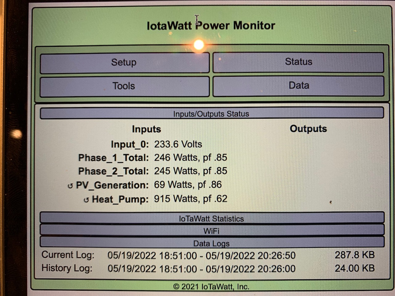
Here you can see the output with both clamps on the Live 3 cable, both showing the same, positive, value

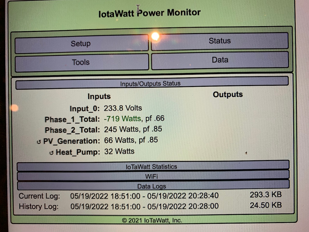
This is immediately after I moved CT clamps 1 and 2 from the live 3 feed to the live 1 feed, suddenly changes to a negative value, even though the clamp is the same way round and the PV generation is only 66w. Clamp 2 is showing positive because I haven’t set it to allow negative readings but if I set it to allow them, it also shows a negative value.

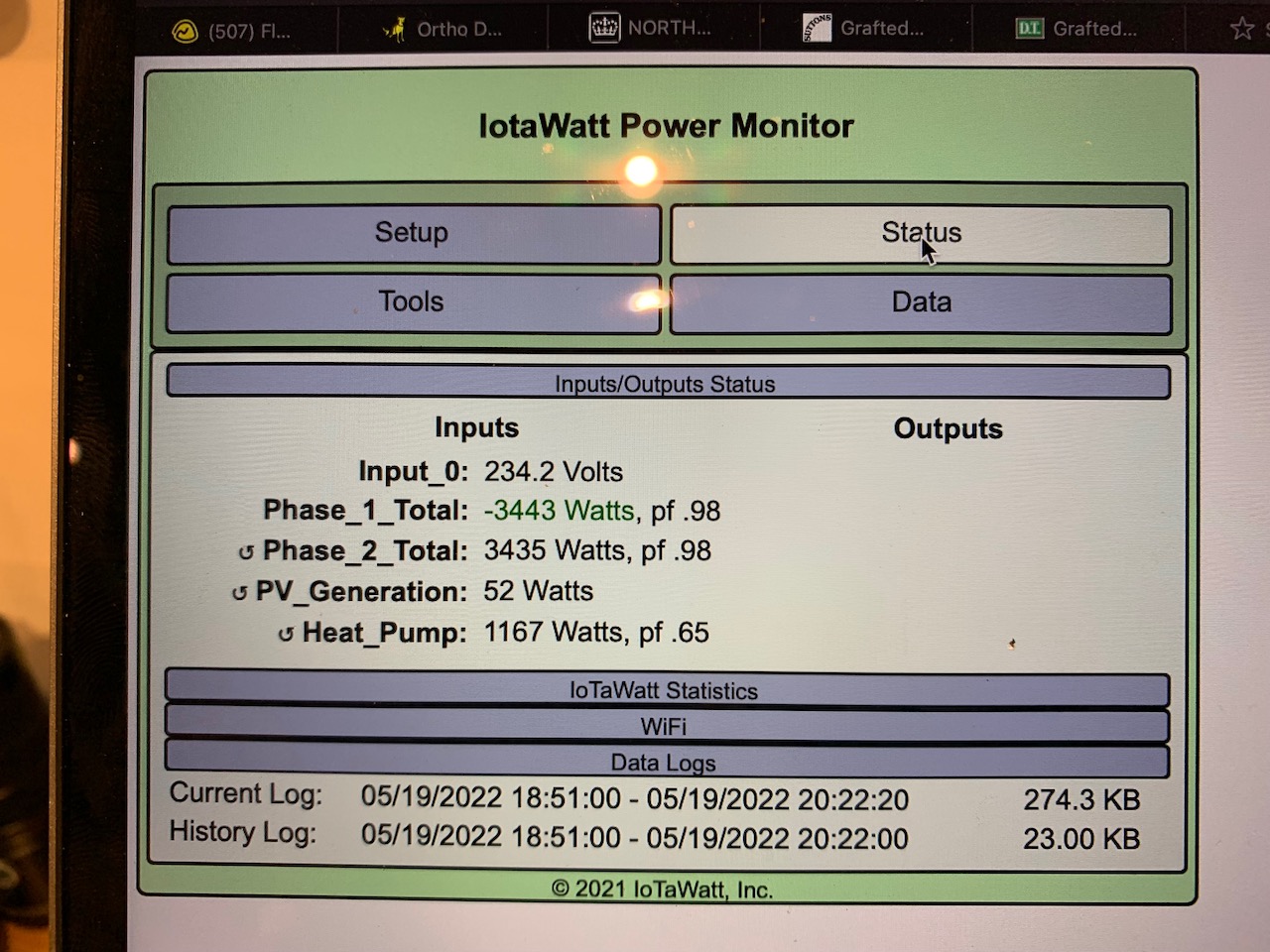
And finally, turned the heat pump on and it registers a large negative increase so it’s definitely showing the power flowing but in the wrong direction. I’m very puzzled now.

Can any one suggest what’s going on here?

Maybe you have split-phase, but I doubt it. Your meter is a three-phase meter. 3x230V/400V. I’ve seen some true 230V/460V split-phase in Australia, but not in the UK. I suppose it’s possible that the meter would work with split-phase, but I think it’s two phases 120° apart. With split-phase, the two are 180° apart. It’s a whole different ballgame and we measure them with different methods.

The easiest way to determine which it is would be to measure the voltage between L1 and L3. If it’s ~460V then it’s split-phase as you say. If it’s more like ~400V then it’s two phases of a three-phase supply.

If you cannot know the voltage, we can embark on a series of experiments to figure it out. The first would be to determine which of the two legs the VT is connected to. One method would be to connect a fairly high power appliance like a hair-dryer to the same power-point as the VT. Cycle the hair dryer on and off and note which of the two L1 or L2 registers the power usage. Note the amount of the increase when on. Post the results.

Ah yes, forgot about the phase issue. It’s definitely split phase, we tried to have three phase installed when we moved to the farm 8 years ago but were given a quote of £70k given how far the connection is. A few years ago when the power company were replacing the old 16kva transformer on our pole, we paid to have a 50kva split phase supply installed to future proof for upgrades.

I’ve opened up the consumer units on each phase and they measure 240v per phase and 490v across the two lives, L1 & L3, so yeah looks like definitely split phase.

How should I change the settings for the CT clamp on the Primary house phase?
Also, does it matter that the PSU and voltage PSU are both plugged in to the secondary phase where it exits the house?

Thanks for building Iotawatt, it’s an amazing system and I’m really looking forward to playing with it over the coming months and integrating it with the current PV, the new heat pump and the battery system I’m in the process of installing.

For now, I’ve reversed the Live 1 CT in the setup and it seems to be operating as I’d expect as we’re currently exporting PV on a sunny day.

OK, split-phase. If you read the docs concerning split-phase, the two mains CTs are installed with opposite orientation. So you’ve done that and things are better.

Your status displays above show a voltage of 234V. You measured with a meter and got 240V/490V. I think at a minimum you need to do some calibration of the VT. Do you have a good RMS voltmeter? See the docs for how to calibrate.

If you have or can install a power point for L1, you may be better off to add another VT for that leg and treat the two as separate power systems. I don’t know how accurately the split-phase “splits” the voltage. In North America we use a single transformer with a center tap. Those yield pretty even leg voltages and so using a single VT is reasonably accurate. If for instance your power company used two separate transformers, or has connected other loads to one of the legs, the two might not be as symmetrical as expected. So at a minimum checking for that symmetry or better using two VTs are advised.

Thanks very much, at least I know now why the readings were as they were and how to fix it.

My multimeter isn’t an expensive one just a budget DMM, I’m currently googling True RMS meters and will pick up one once I’ve decided on the model, then I can do calibrations.

If I put a second VT on, would I have to use a second Iotawatt system for that phase or can you put a second VT into a single unit?

Transformer wise, we have a single big transformer on a pole near the house, I don’t know enough about how those work but I can probably ask my pet sparky who’s likely to know, or I might even be able to get him to come round and bring his meter with him to help me calibrate things but having a decent meter would probably be a good idea anyway for testing and checking

OK, so I have a choice on a couple of meters, the amazon commercial meter https://www.amazon.co.uk/AmazonCommercial-Compact-Digital-Mulitmeter-Temperature/dp/B083V7N12H/ref=sr_1_3?crid=15R9Q8ISR82AB&keywords=90DM610&qid=1653056223&sprefix=90dm610%2Caps%2C51&sr=8-3 which for £40 looks a steal for my sort of uses and seems reasonably well thought of online or the EEV blog badged Bremen 235 EEVblog Brymen BM235 True RMS – with probes – Simon's Electronic's for twice the cost.

Can’t afford or justify a Fluke but if the Amazon reads consistently it seems like a good option. Any thoughts on it?

You only need the meter or other reference once, so you might consider borrowing one or the sparky. Also, at least in the USA the Kill-o-Watt devices give an accurate voltage reading. If you are using the Ideal VT, it’s probably pretty close.

Yes, you can have up to three voltage references. Typically used for three-phase, but can be used for split phase as well, especially where you probably don’t have 480V loads so the two legs are effectively independent systems. Additional VTs use inputs 13 or 14 and so you lose those inputs for CTs when used for VTs.

OK, that’s probably a center tap so both legs should be reasonably close. You might just take a meter reading and record the data and time, then another in a few days and see if the IoTaWatt and meter agree. If they do, within say 1%, you probably don’t need to do anything with calibration or additional VTs. There’s a good chance that’s the case.

Decided to treat myself to the amazon commercial meter. Both my other multimeters are just very cheap ones and several years old so it’s nice to have something of better quality and it allows me to do calibrations when I want going forward.

I’m using the ideal VT, bought from openergymonitor so know it’s a proper one. Will calibrate it and see where we are from there. If needed I can get another VT and wire the appropriate plug on to it. Not much is on the L3 phase, just the barn and workshop and, eventually when we get an EV, the charger for it will be on that phase too.

I’ll take some readings with the new multimeter over a couple of days and see how it all compares and then come back to you. Thanks again for all the help.