The numbers don't add up - RESOLVED

So I just got my Tesla back from the shop where it has been for the past few weeks, during which time I got Iotawatt up and running.

Just plugged it in, and somehow it’s not being accounted for properly.

I have a split phase US system. Setup is as follows:

So how can I be using over 8500 watts just on what’s connected but only showing 4600 watts on the mains legs?

Joe

Hi Joe,

The EV charger is 240V, so what you are showing on Main_2 is definitely too low. I see that you have the clamp type CTs. Those usually have small pieces of paper between the mating surfaces on the clamps to protect what needs to be a very smooth surface from chipping or corrosion during shipping. If you unclamp it and look inside, I’m betting one of the papers are still there. Just blow it out and reinstall.

If that doesn’t do it, can you post a picture of the clamps installed please?

Thanks

Well, there was no paper, but opening, checking, and replacing the CT seemed to do the trick… Color me confused but happy.

One other question - the Tesla CT was showing as reversed. I checked the box to account for that, but when I had the panel open I checked and it is facing the same way as all the rest (open side/clip facing out). Any reason why that would show as reversed? Should I be concerned at all?

Yea, I was going to suggest a little housekeeping once you got the mains right.

It looks as if the Main_2 is reversed now. That’s OK. I’d rather you check the “reversed” box in the input setup than mess around with it.

The previous set of status/setup indicated that the Tesla input had the “reversed” bod checked
image
and at the same time, the status screen showed it as reversed.
image
So I’m not surprised it was installed correctly. You must have unchecked the reversed box because now it doesn’t show as reversed in the status display.

Actually, I haven’t unchecked the reverse on the Tesla input - it is still selected. I don’t know why it isn’t indicating as such.

I just checked the reverse on the Main_2.

It reads correctly either way, but something had to change. Possibly you moved the CT to the other conductor, or physically reversed the CT?

Nope. I might have touched it gently with a finger, but I certainly didn’t open/move it.

Tesla and Main_2 are circled here:

Here’s a closeup of the Tesla and other CTs to show that they are installed the same way:

And here’s Main_1 (left) and Main_2 (right):

I will make a note to add this to the documentation. Split-phase load centers have two 120V “legs”. They are the circuits created by each of the two mains and a neutral conductor. When a load is connected to both of the mains, it is 240V, when connected to one of the mains and the neutral, it is 120V.

The 120V legs are exactly opposite in phase. That is to say that when one leg is positive in voltage, the other is negative. So current in the two legs is opposite at any moment.

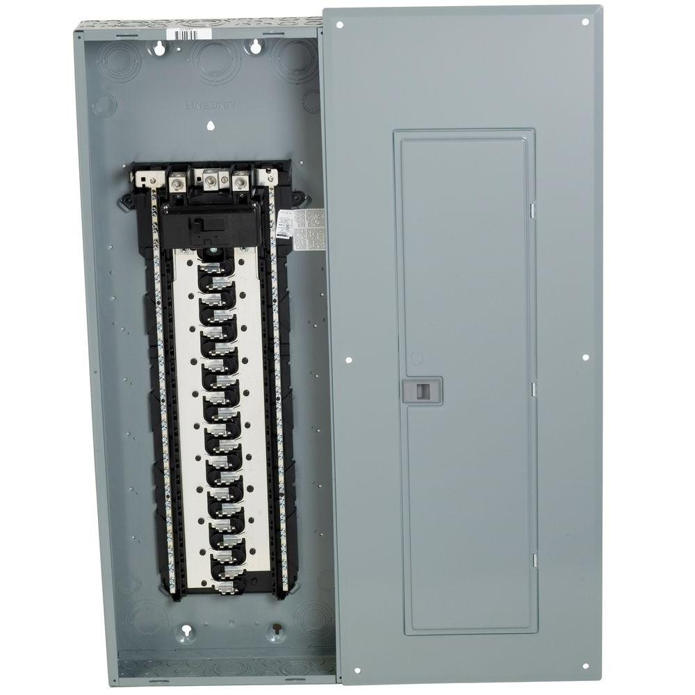
Your voltage reference transformer is 120V, and so is connected to one of those legs. It reflects the voltage in that leg but also the exact opposite voltage of the other leg. Here is a typical split-phase load center with no breakers installed:

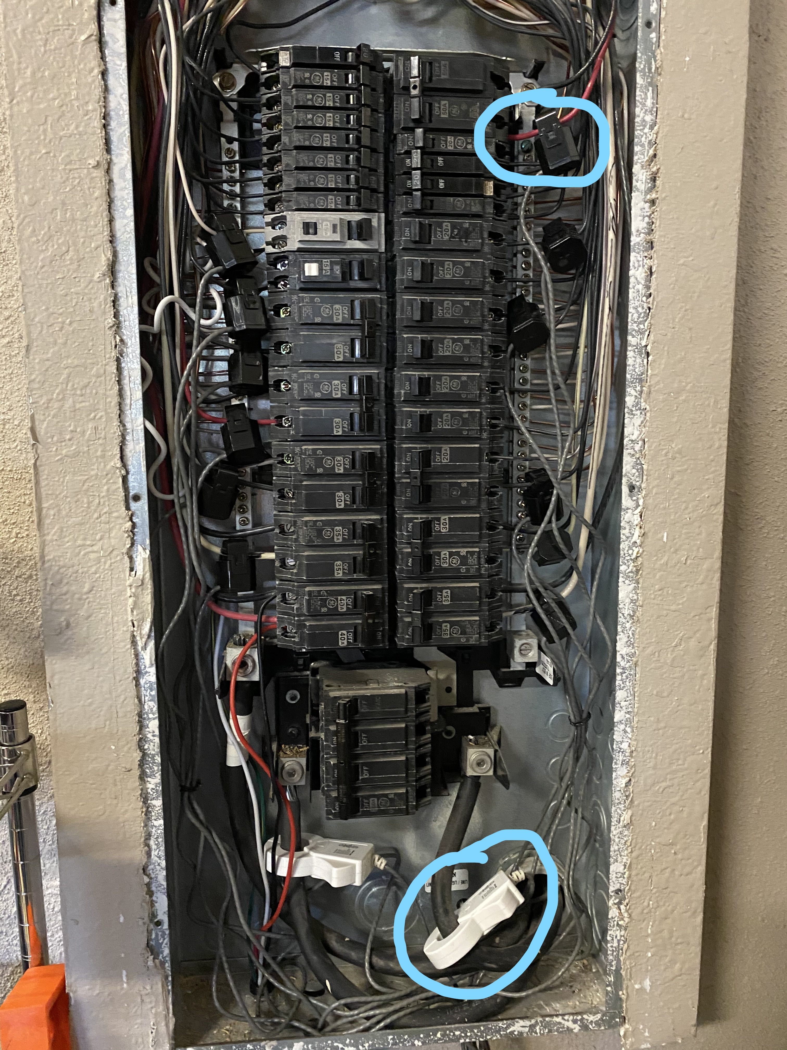
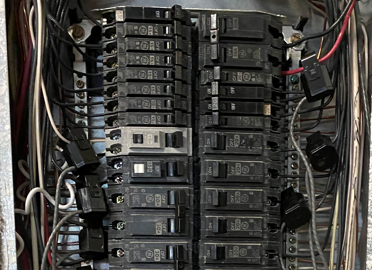
You can see that the breakers alternate between L1 and L2 as you go down the rows. To complicate this slightly, your load center is mounted in an inverted position with the mains at the bottom. So what is normally the left main and called L1 on a panel with the mains at the top, is your right main at the bottom that you call L2, and visa-versa.

Starting at the bottom, the first row is your L2, then alternately L1 and L2 as you go up. Near the top, you have some double breakers that are both the same main corresponding to the full height row they are in.

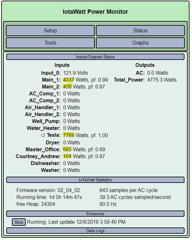
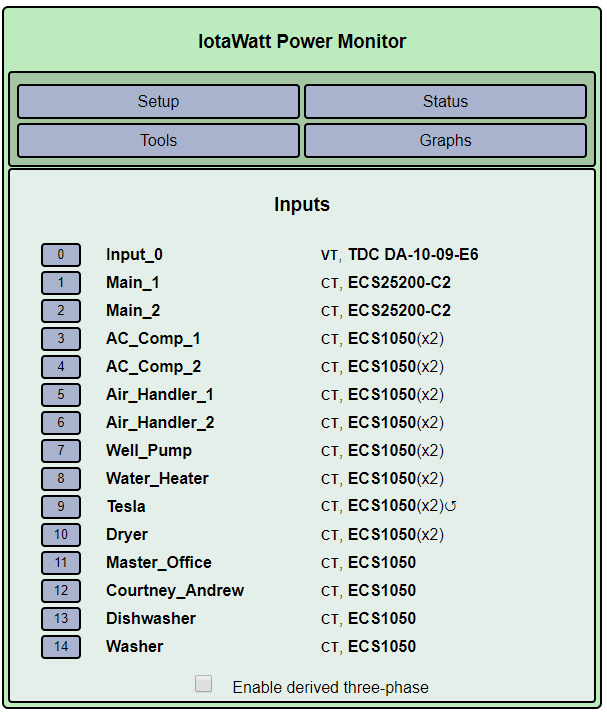
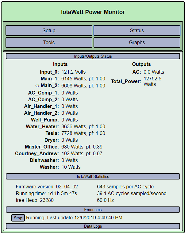
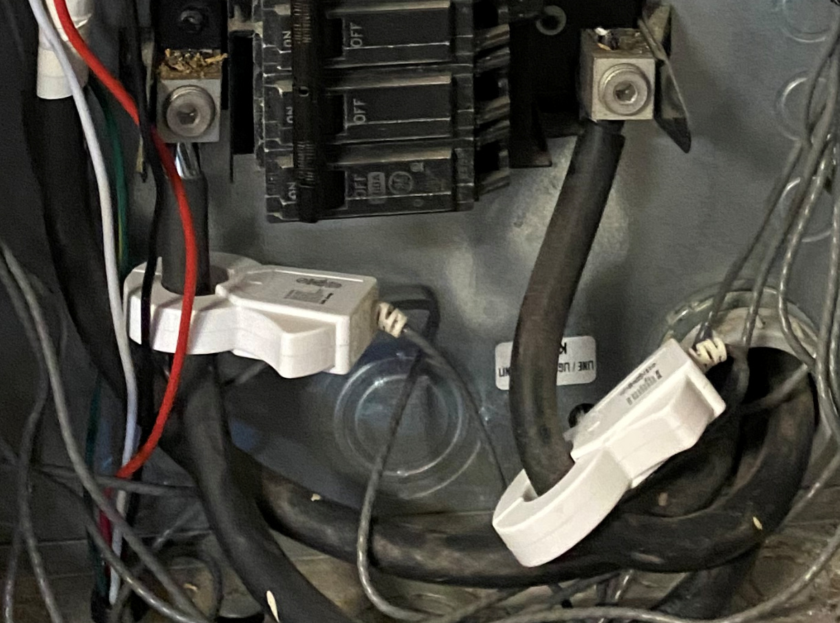
In your panel, you have the CTs oriented one way on the left and the other way on the right. So you get that they must be different for each main, but not that they alternate in rows rather than side to side. In your box, the odd rows correspond to the right main that I believe you call L2, and the even go to the left main that you call L1. So going up from the bottom the rows are L2, L1, L2, L1… The Tesla CT is on an odd row, so is your right main, or L2. Since it’s reversed, we now know that odd rows should be oriented with the arrow (and wire) away from the circuit breaker. Likewise the three bottom CTs on the right are probably reversed and the top CT on the left is probably reversed as well.

For the 240V circuits, if the CT were on the other conductor (hence another row) it would be reversed by virtue of now being on the other main.

All of this is academic as the IoTaWatt automatically reverses in these situations and reports positive power. It only becomes important with the mains for net-metered solar.