Hi all,
I have a technical question regarding calculating the active power and consumption of a 3 phase motor using an Iotawatt.
My mains supply is 3 phase + neutral, with 230V between each phase and neutral and 400V between any two phases.
The motor is a 3 phase motor and doesn’t use the neutral, and I have no reason to assume that it isn’t balanced with an identical power factor on all phases.
The Iotawatt is set up un 3-phase derived mode, and I am measuring 420W on one of the phases going to the motor.
I am trying to calculate the actual total power consumed by the motor, and I have some doubts about my approach. I have been using
420W / 230V (assumed by Iotawatt) * 400 (actual between 2 phases) * 3 phases
… but that yields over 2kW, when the motor spec says 1.02kW.
UI cos(phi) gives 420 * sqrt(3) = 727W which may be correct?
Or is it rather 420 / 240 * 400 * sqrt(3) ??
Where is the truth?
Thanks!
It doesn’t matter that the motor is connected delta. The power is the total power measured on the three conductors. So you can put a CT on each, using the correct 4 wire phase reference for each.
I agree that they may all be nearly the same. If you find they are nearly equal, you may want to simply monitor one and multiply the measurement three.
You can do it this way because you have a four wire feed. If you had a three-wire feed, you would need to know the phase to phase voltage and with that, you could derive the other two and measure power to the motor with two CTs.
But given that you have a 4 wire system, measure the three and add together. If they are truly symmetrical, you will get about 1.2 kW, which seems reasonable for a 1 kW output motor under full load. That would be 83% efficiency.
Still having a hard time wrapping my head around this: I also have a 3 phase water heater (again no neutral used), and I unwired one of the phases to take it down to around 1kW so that it runs on my solar panels.
I have an Iotawatt CT on one of the 2 phases still in use, I assume that in that case the actual power is
<iotawatt reported power> * sqrt(3) ?
Thanks!
If it makes you feel any better, I have a hard time wrapping my head around three phase math as well. And I’m no expert. I’m a programmer. I research the algorithms and implement them. In many of these cases, I simulate the environment with a spreadsheet model. Got a pretty good track record, but a real power engineer could make me look silly.
Like the motor example, the I base my answer on the fundamental principle that the total power is the sum of the power delivered by each of the contributing phases. In this case, with a four-wire system, we can measure the power delivered by each phase because we know the reference voltage. It’s a little different if there is no neutral for reference.
So the answer is that the power is equal to twice the IotaWatt reported power of one of the conductors. Don’t get carried away by the notion that the voltage between the phases is different than the voltage between each conductor and neutral. It’s all baked in the cake because current will vary depending on the effective voltage.
This problem is exactly the same as when a 208V appliance is connected to a US 120V/208V three phase system.
Unrelated to the power measurement though, you should consider what disconnecting one conductor does to a three phase heater. The intuitive expectation is that power will be 1/3 of the full three-phase power. That’s not the case. Picture the heaters as a triangle with each side being a resistor. When you disconnect one conductor, the two “disconnected” sides of the triangle still heat as they are now in series between the remaining two conductors and will together produce half as much heat as the other side because the resistance is doubled and the current is half. So the net effect is that the overall power will be 1/2 the full three phase power.
Damn, I totally missed what you point out about 2 sides of the triangle still being powered, good catch! Fortunately I can easily fix it since each individual connection is independently accessible.
Assuming that I fix the above, I definitely don’t get why power would be twice what iotawatt reports: it integrated U*I but assuming a sinusoïdal U between phase and neutral; not too sure how that translates to the U between two phases, which may not even be a sinusoid?
Franck
The tension betwen two phases is a sinusoid, but with a different period than the one between phase and neutral according to Wikipedia:

Franck
It has the same period (frequency) of 50Hz.
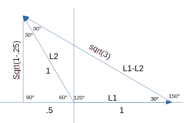
Here is a poor man’s phasor diagram. You can see L1 at 0° and L2 at 120°. The resultant vector when you combine them is at 150° (or -30°).
I’ve added a magnitude of 1 to each of the L1 and L2 vectors, then formed a right triangle to the X axis from the L2 vector. We know that the sine of 30° is .5, so that’s the base of that triangle. The height is the square root(1-.25) or square root of .75.
Now solving for the L1-L2 vector length = sqrt 1.5² + .75 = sqrt(3).
I gotta get a better math plugin.
It’s all baked in the cake. It’s a single phase circuit, so the current at both L1 and L2 is the same. If you had a voltage (and phase) reference for the L1L2 vector, you could integrate that over the current signal and get real power. But we don’t have that (actually, that could be derived as well, but lets not go there). The next best thing is to take the voltage at each leg times the current. At any instant (almost) that will be different on each leg, but the total will be the same as if you had used current times an L1L2 reference.
After a complete cycle (starting anywhere for 20ms), the total of the two will have integrated over a full cycle and each side will have integrated half of the power. So double one side to get the total.
My head is hurting, I will trust you on this one 
Thanks for the help!