As a disclaimer, I am very green with all things IotaWatt at this point. I read as much as I can but still feel perplexed.
Pertinent Details:
US Based
3 Phase
1 Main , 3 Sub panels
1 Wind Turbine
Iotawatt 5, using derived phase for my measurements
I currently as trying to configure the three phase CT’s but am running into a snag and unsure if it has to do with my turbine or if it is not connected to my main panel. I am told it has an interconnected WECS (unsure what that means).
Taking a step back though, I still do not believe I have my three phase configured correctly. The first clue was that my data graph is showing 2 positive power legs, and 1 negative. The negative reading leg is the confusing one. Even more odd is that it seems to mirror to some level the other 2 legs, but not exactly.
The three sub panels I have are for extra breakers inside, a garage/cooler, and additionally and most importantly, the wind turbine shed. How it is all connected is still over my head at this point, but its the main reason I began looking into a monitoring device.
Secondary disclaimer, the property that I purchased had a turbine installed but little to no documentation.
I am waiting on more CT’s to monitor that particular breaker and if it has any type of reverse power. However, I recently needed to clean up my panel box and shut the main down and had no reading coming from that during a very windy day. If anything was going to back feed that was the day for it to happen.
I’ve read a bunch of forum posts up to this point and a lot of times I see a solar panel showing a positive figure on the power chart and the source as a negative. Is this correct?
Pardon my confusion and my disjointed post, any help is appreciated!
Also, The CT’s are indeed pointing the correct direction. Towards the breakers as I am to understand.
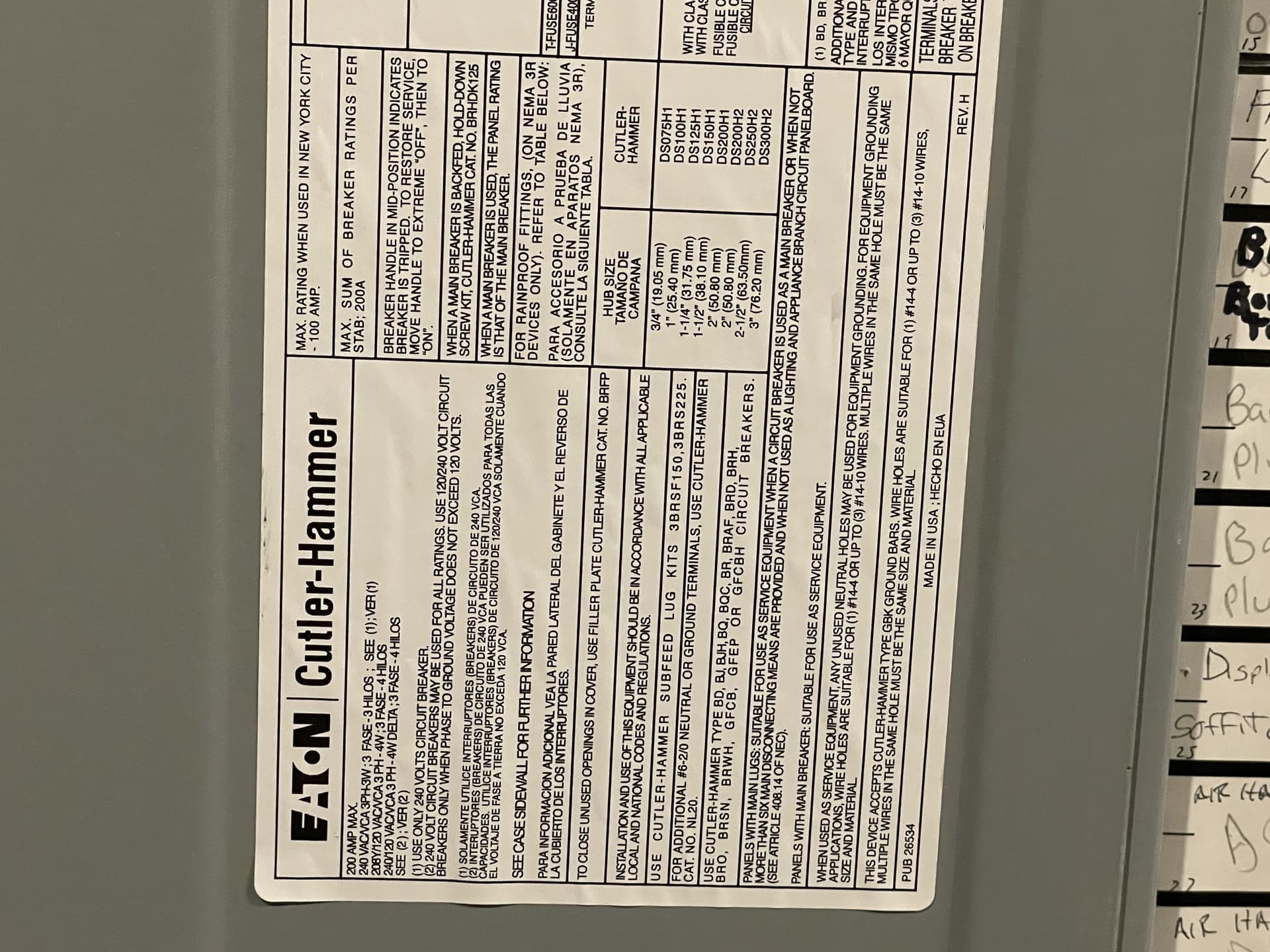
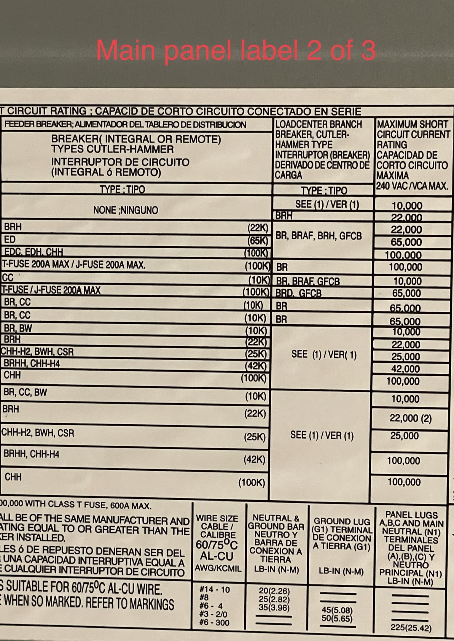
High res pictures of the panels would be good to have in this thread for reference.
The wind turbine is probably single phase. It could be connected to a single phase at 120V or to two phases at 208V. The single-phase 120V scenario would explain one of your mains being negative (back feeding) while the other two are positive.
Typically, a home wind turbine would have a generator that synchronizes to the grid frequency. Like a PV inverter, it will shut down when the grid drops both because it doesn’t have anything to sync to and because of the danger to line crews if local generation energizes an otherwise dead transmission line. So that it doesn’t do anything when you shut down your mains is probably normal.
My advice would be to start with the derived reference setup procedure in the docs. I assume you are using derived. You should either shut down the wind feed or wait for a time when there is no wind.
Once you have that working OK and can reconcile it with your meter, you can determine the phase assignment for each breaker by its position in the panel.
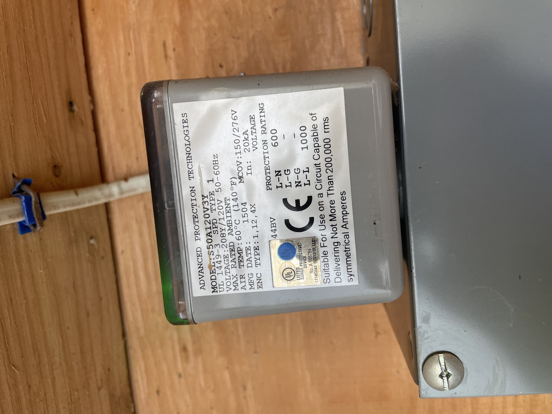
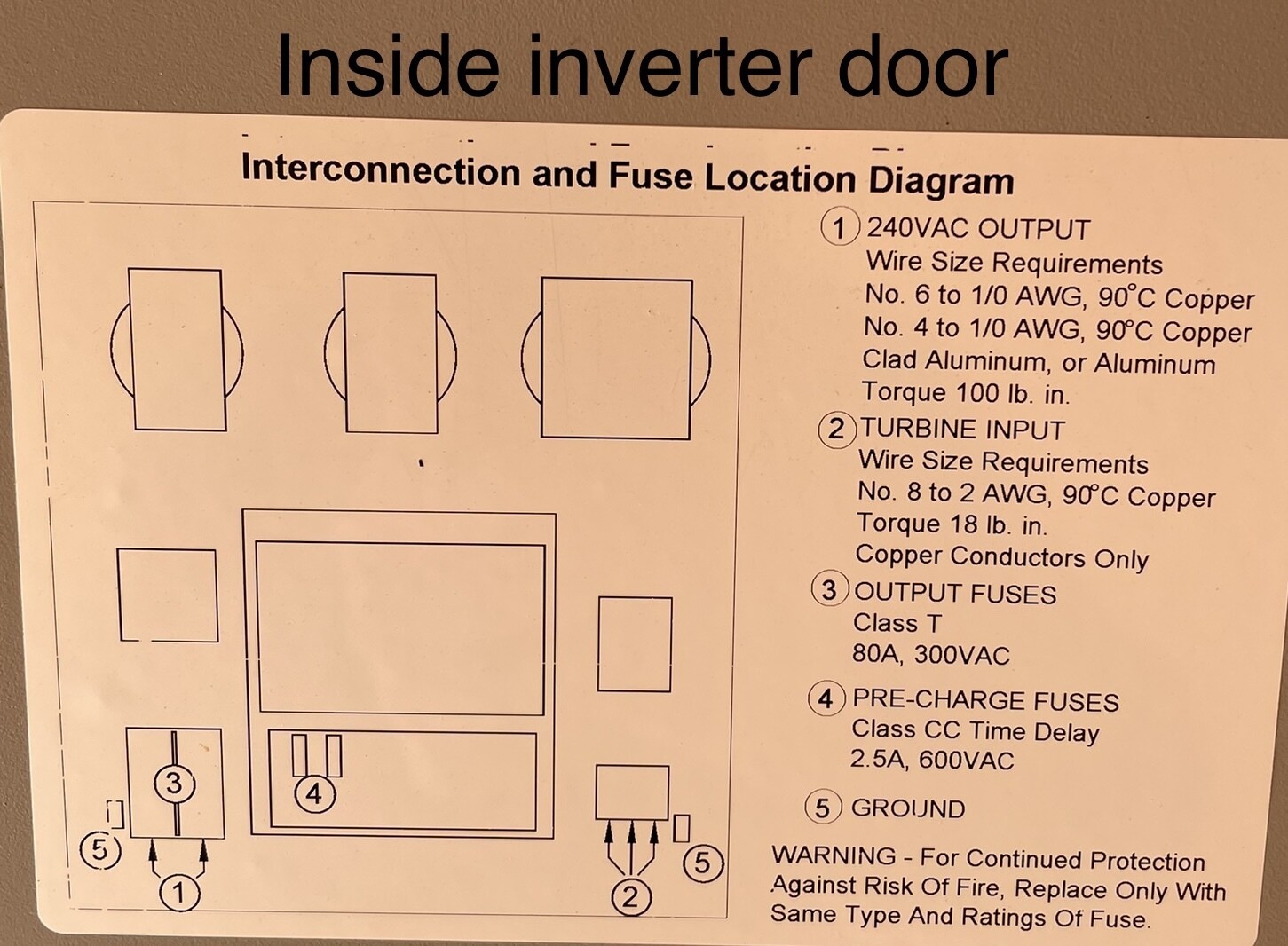
So the first image is of some type of surge protector I believe. Not 100% sure about it, but that’s my educated guess.
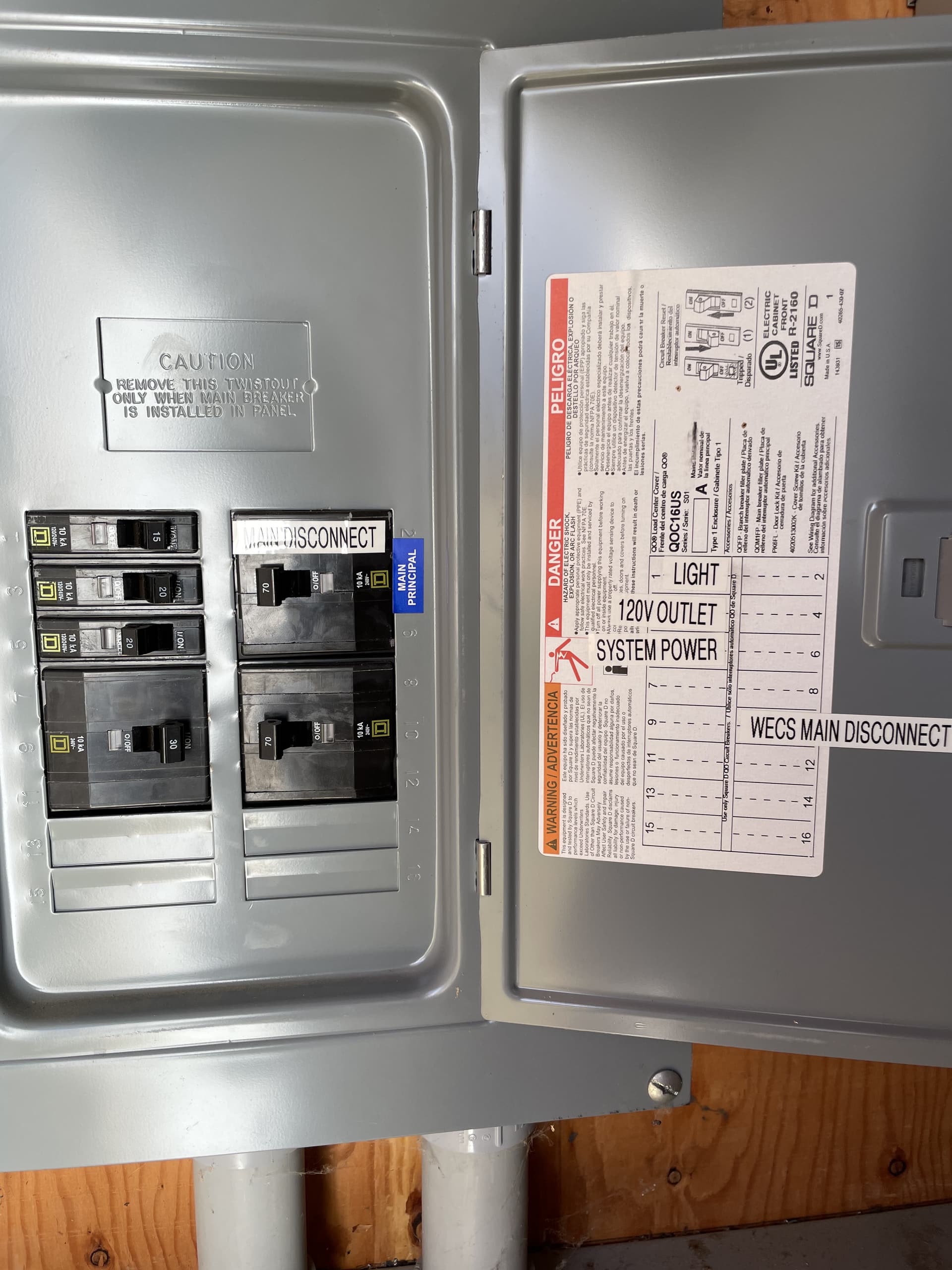
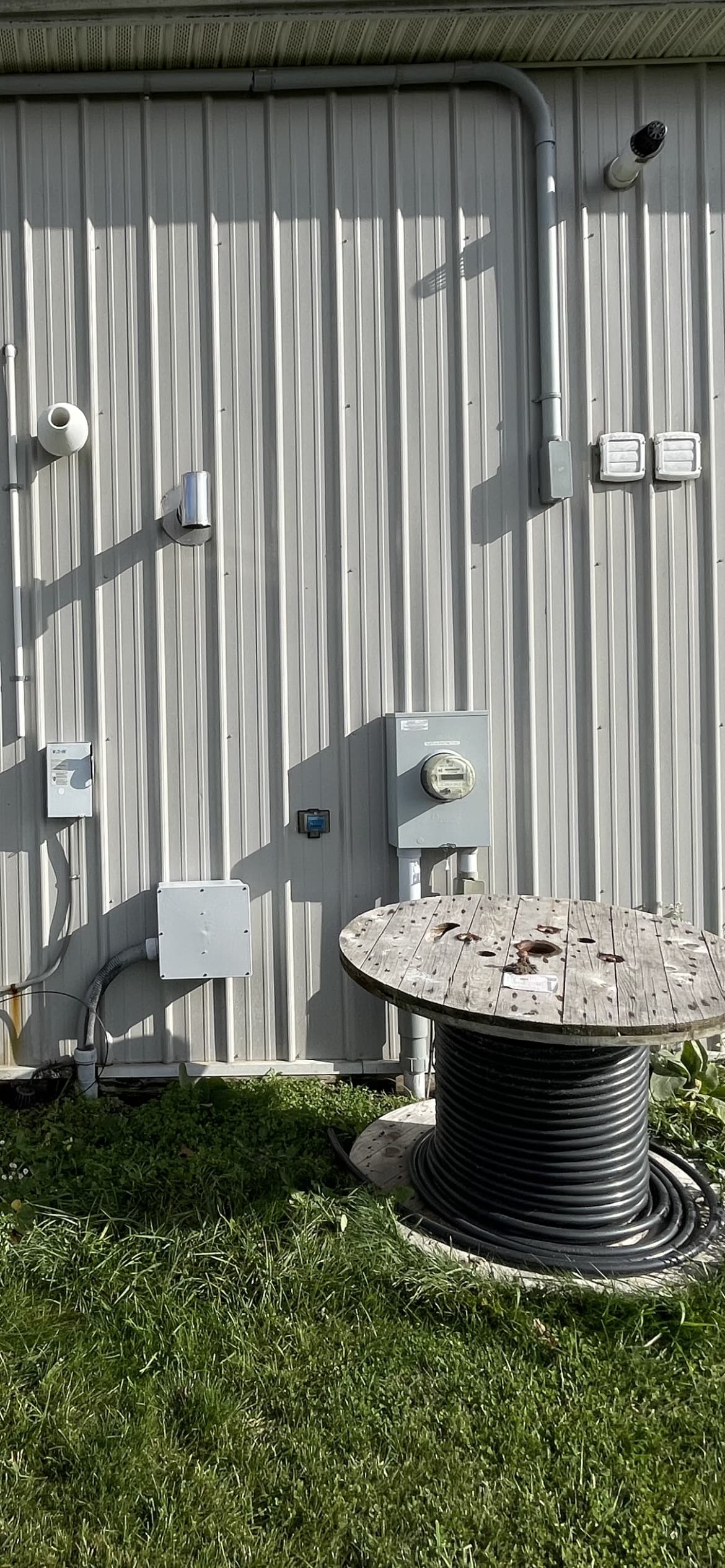
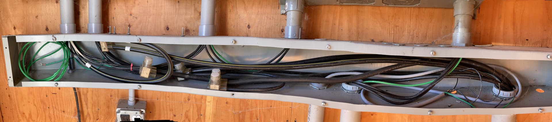
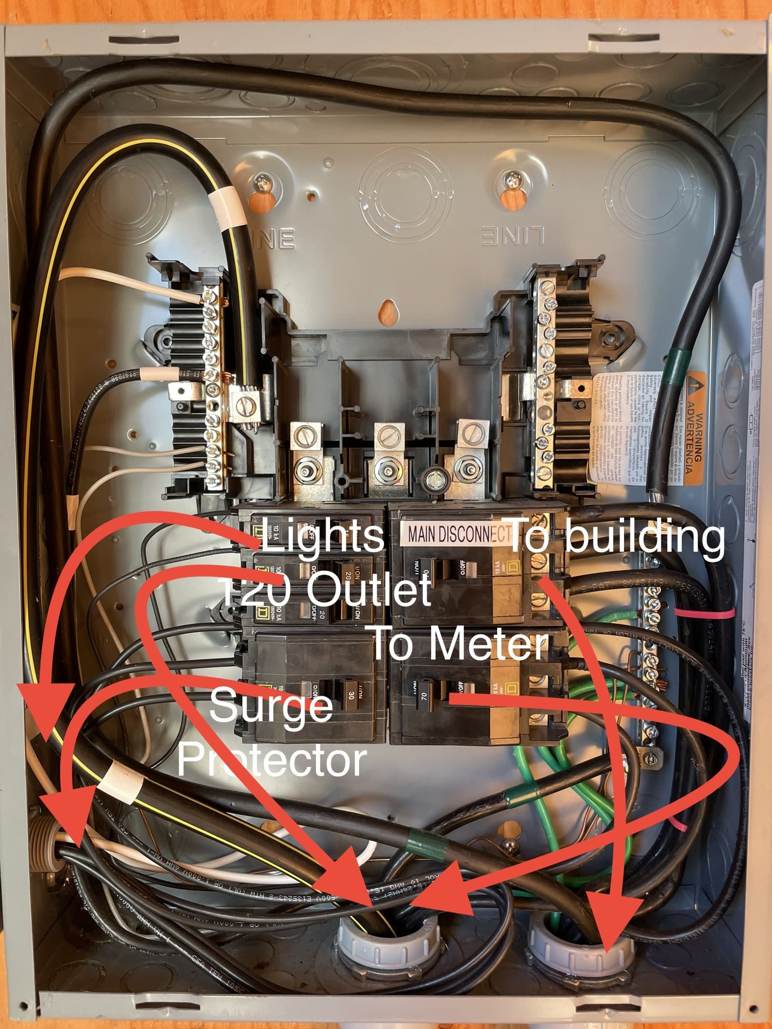
The second image is of the setup in my wind turbine’s shed, with the third image being of the breaker descriptions. I had a good bit of snow so it wasn’t easy to get out there and take a look inside of the panel, with the cover off, but it’s better than nothing at this point - I will work on snagging a shot of that in the short future. I don’t know if you are able to see it or not on that layout shot, but the top right corner of the meter says “Grid —>”
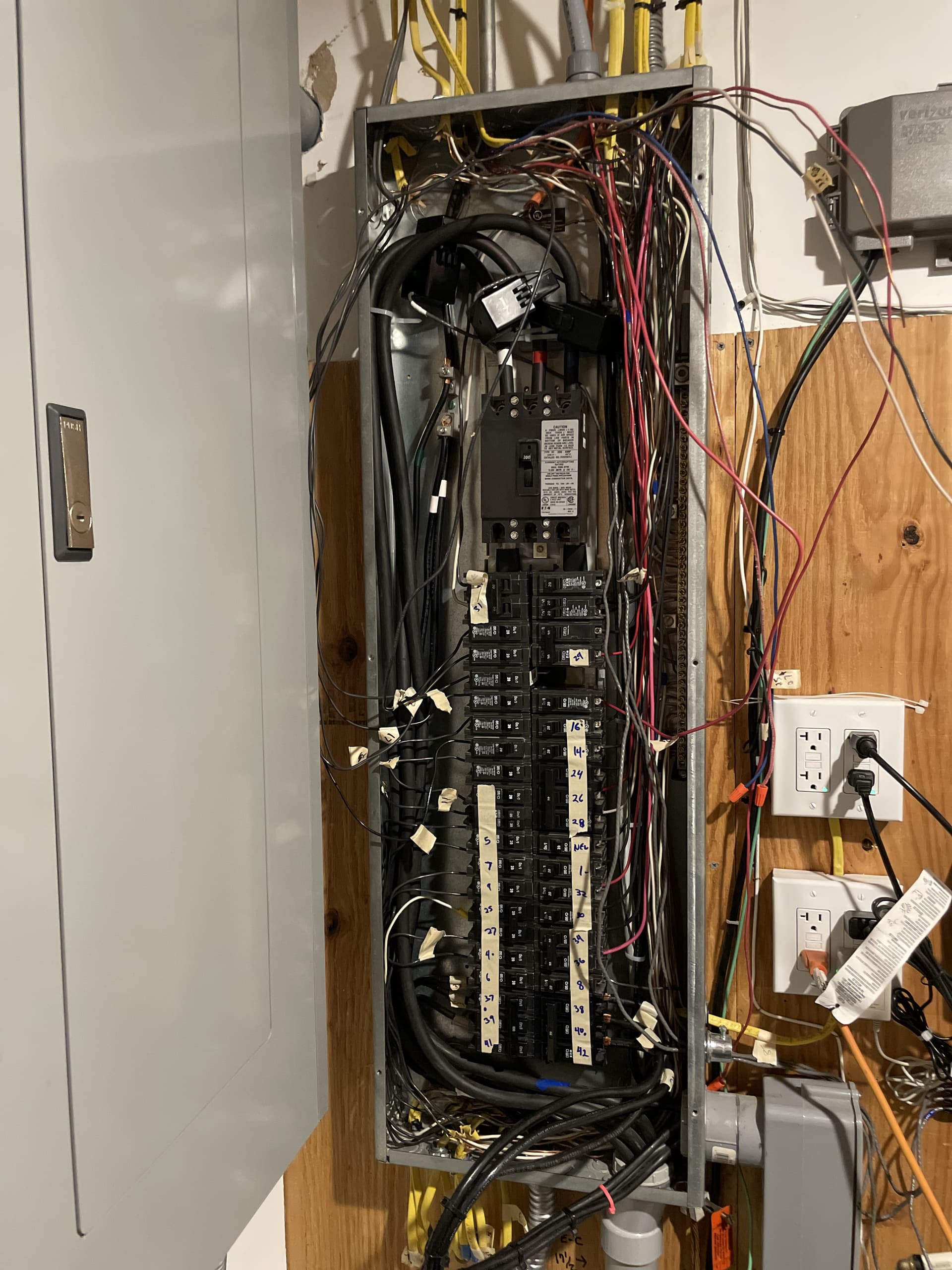
The last is the main panel in my building. I have a touch more cleaning up of the wires to do still but its almost there. I wasn’t going to be able to fit ANY CT’s in it the way it was prior.
I believe you are accurate in the assumption that the inverter drops when the grid does. I do specifically recall a conversation where I was told if the shed does not have power, power cannot be generated.
Lastly, in regards to the setup procedure, I did follow that to the best of my ability, and you are also correct in my use of derived reference. I would like to use the actual if possible, especially if one of my legs is back flow. I feel like that could throw a wrench in a derived method.
I need to get another shot of the inside door of my panel but had a diagram that appears to have the rails that the breakers snap into in a sort of “S” configuration. There are black squares that go in a pattern (for lack of better description at this point) of A B C B A B C B A … and so on. Is this demonstrating where each of the legs are the primary phase?
Hope this clears up a little and creates less questions than get answered!
I think it’s likely that your service entrance goes to this turbine shed. The main there is your grid connection. The WECS is the “Wind Energy Connection System” where the turbine power is connected and what I think is a 70A three-phase breaker that probably feeds your house.
If those assumptions turn out to be correct, it would make sense to use an IoTaWatt in the turbine shed to measure your mains, wind production, the mains to your house and possibly whatever the three 120V breakers lead to (probably lights and service plugs in the shed).
If you want to further break down your house usage, a second IoTaWatt would be advised.
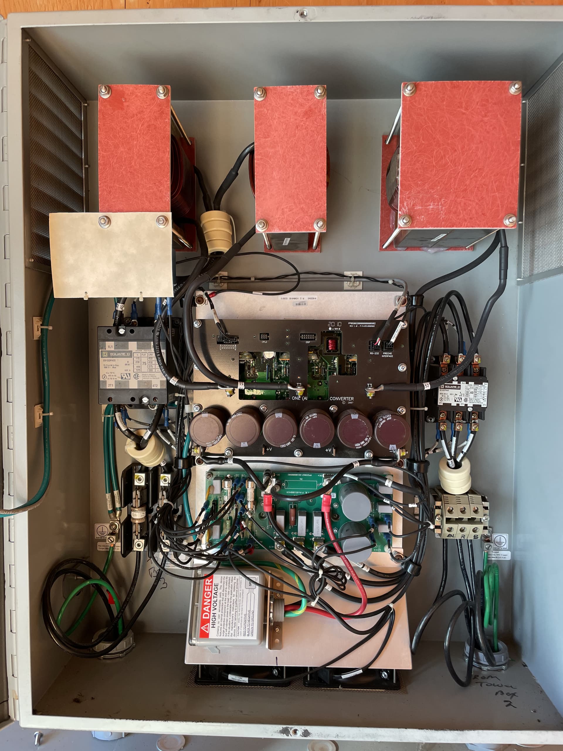
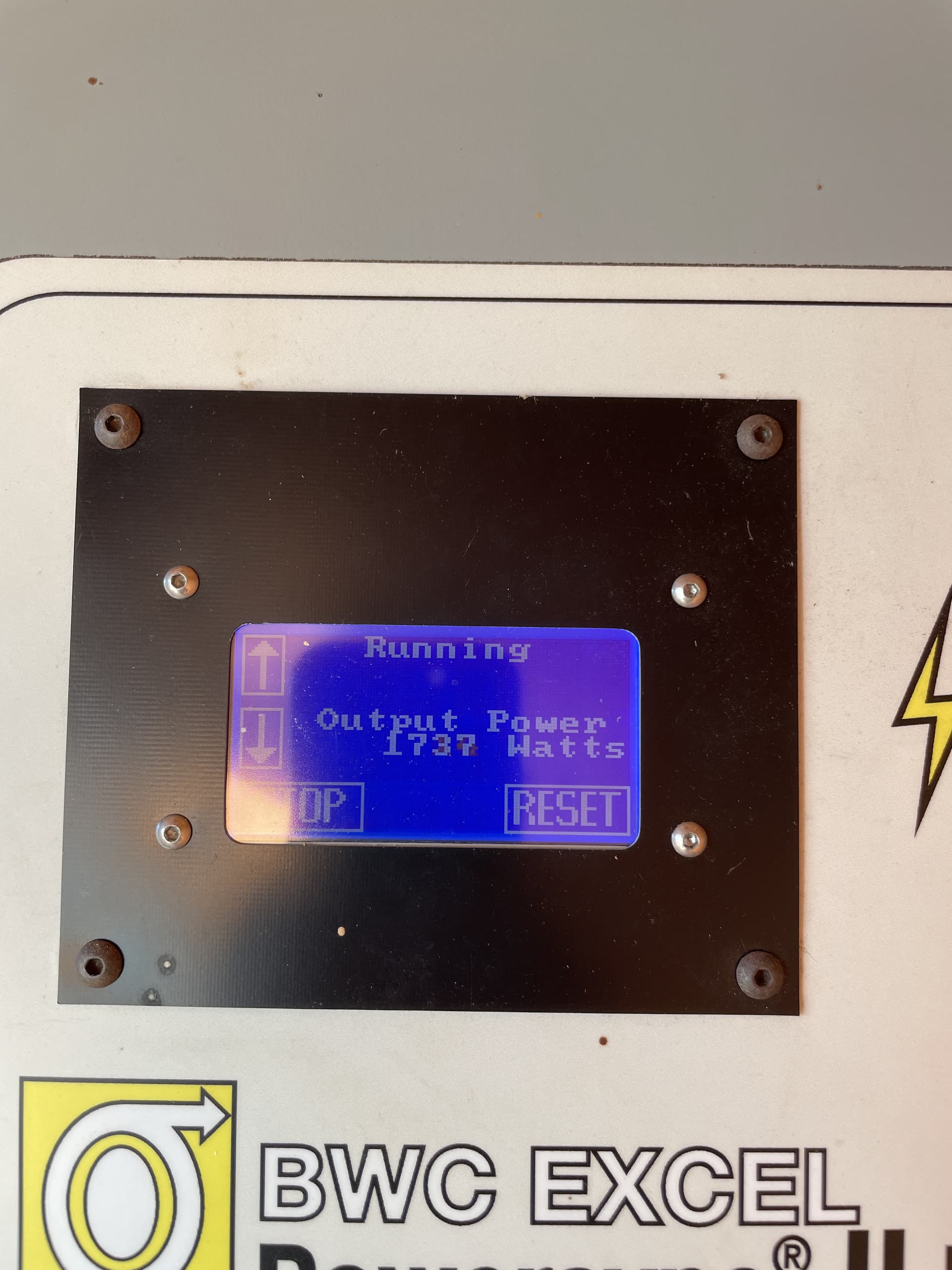
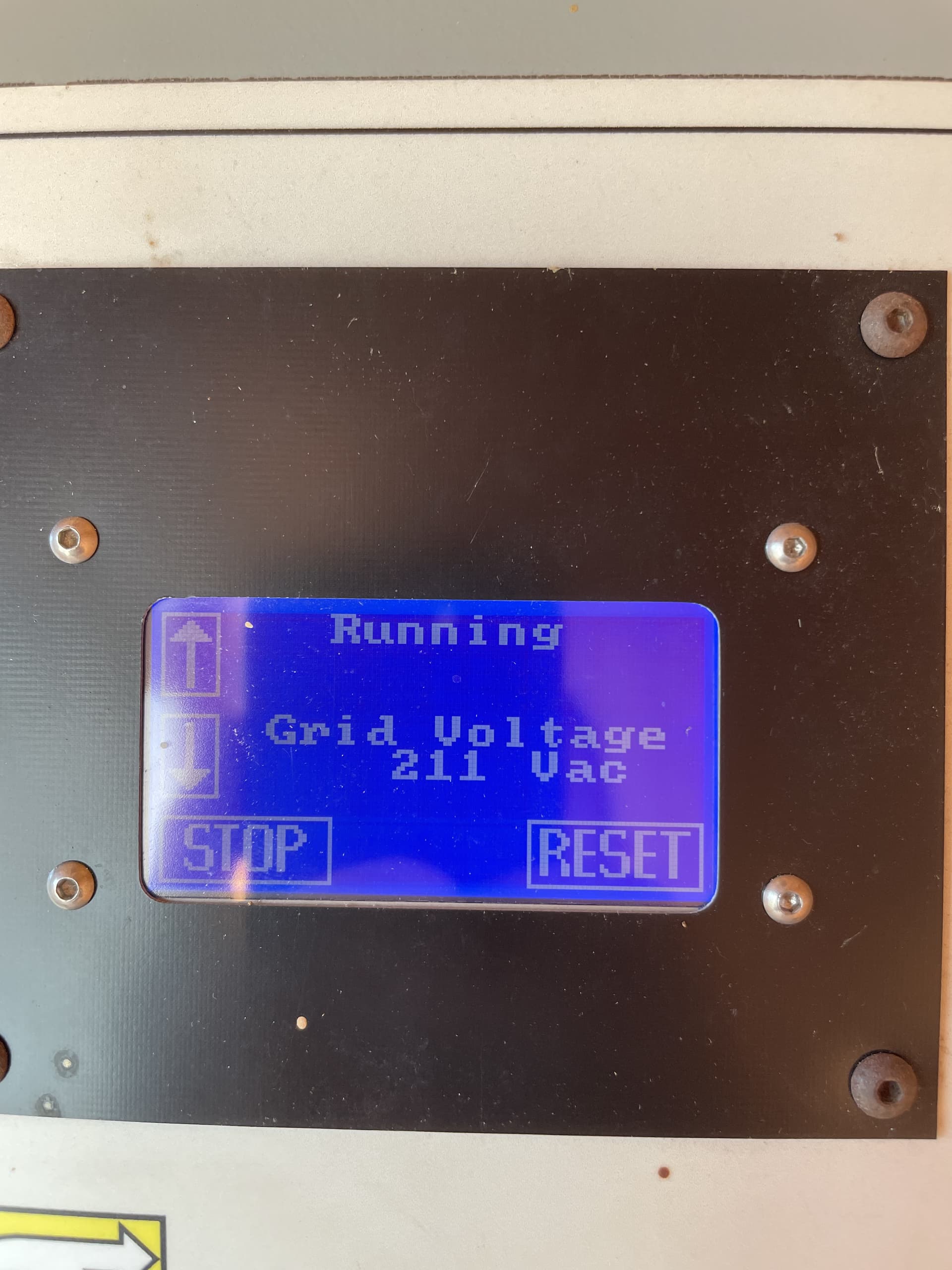
The turbine shed has an inverter on the right that led me to an owner’s manual for the BWC Excel Wind Turbine. I believe you have the three phase version PSII126208 with 208V single phase output feeding two of your three phases. There is also a display on the front of the inverter where you can read out a lot of operational metrics and control the operation of the turbine. For example it’s possible that your unit is stopped for some reason and you may need to reset it from that display. The manual explains more.
This is worth the price of admission! The two contacts I have had as well as my utility company have been unhelpful on this beyond belief. Thank you for at least getting me to a manual, I should have googled that name on it, but the only other reference material I was given was 2 pages total.
I do know about needing to reset the windmill if it is free spinning as that indicates no resistance and therefore no power generation.
If I don’t have wifi near the shed, is it possible to have a unit out there? I obviously can’t have it push data to InfluxDB Im sure, but could I use its local wifi network to see the information? Additionally, I saw the reference to the 70A dedicated breaker. I do have that in the main building. It’s the bottom right triple pole breaker.
Apologies for my assumptions, but at this point I am still wrapping my head around it all. Am I correct in understanding that according to your prior post, I have 3 legs for my 3 phase, but 2 are run directly from the street service at the brewery, and the third originates at the windmill and then is tracked to the main?
I have two larger conduits that enter the main panel in my business. One is exclusively the 3 main legs and the other is the 3 legs that connect to the aforementioned 70A breaker. I have a picture attached that shows the exterior of the building, so you see the meter placement as well as where the other lines are coming in. I need to verify, but I think that if I cut the 70amp breaker inside the main building it will also cut power at the windmill. This is opposite to your thought on directional flow. Additionally, we use way more than a 70amp breaker would support on site. The main service is 200 amp, and I need to either get a secondary service or increase to 400 amp. That is neither here nor there at this point though! Also, and while it is POSSIBLE, the windmill was installed after the building was built, so I think it probably had its service run from the building – at least is my presumption.
I plan on adding the CT’s on the 70a circuit and seeing what type of readings I get. I have a half guess that it would only be the usage from the shed, so whatever power is required to run the windmill itself. Over the next couple of days I hope to get to the shed and take off the cover to see what I am dealing with.
Also, I am planning on double checking all of my main CT’s to ensure I have proper configuration.
Should one of the 3 legs at the main panel in the building (not shed) actually be a supply from the windmill, will that indeed throw my numbers off? Or is it still possible to get accurate figures, at least as far as at my main building? I’m not opposed to a second, or possible even third unit, because at this point I am constantly questioning some of the equipment installations and that is what led me to iotawatt to begin with!
Since my last post I did a more thorough read of the windmill and inverter manual. I now believe one of the 70A breakers is the feed in from the inverter. I could not make out much detail in the 200A panel but if you saw a 70A breaker at the bottom of the panel, that is probably feeding the windmill panel through the 70A breaker at the top right. The 30A breaker is probably connected to the surge suppressor, but in any event should be revealed with a picture of the insides.
You can run an IoTaWatt without internet or even WiFi, but you can’t communicate with it without WiFi. You can put an inexpensive WiFi router out there and connect to it with a mobile device when you want to look at the data, or you can figure out how to extend your WiFi out there. Ubiquiti has a number of products with directional antennas that can extend over longer distances. On the other hand, it may be moot if the 70A breaker feeds to your main panel, you will be able to measure wind production from there.
Still not clear about your service. The windmill panel says Square D QOC16US which is a split-phase panel. It may be that you have a three phase panel with a split-phase cover, but as far as I can see, there is no need for a three-phase panel there. The windmill inverter outputs 240V or 208V single-phase.
Your main panel looks to be three-phase at first glance, and the picture is low res so I can’t see any detail. It looks like the lower right is a three pole breaker, so that supports three-phase, but I can’t see any other three-phase in the panel. The main has three cables, but they are color coded White, Red and Black. That looks more like split-phase to me. Three-phase would be Black, Red, Blue. Do you know for sure that your higher voltage is 208V rather than 240V? Your previous observation that you had two positive legs and one negative also suggests it may be split-phase. Can you show the full description of the panel that is usually on the inside of the cover door?
EDIT: can you show a detail picture of the outside meter?
Back again, and it is going to be a little bit lengthy, but hopefully enough info to get some direction.
I went out to the turbine shed and took off the face plate to the breaker box and inverter. I also have skimmed the wiring in the manual you found and may have began to unpack all of this. (apologies for repeat pics, I am attempting to streamline)
This is the setup in the windmill shed. I have internal pics to follow.
The image is a bit distorted in an attempt to panorama the whole thing and give sense of the direction of the wiring. There is a gray wire towards the right side that appears to be connected to nothing, so I have no answers on that.
Starting on the left, this is the interior of the breaker panel within the windmill. I am sort of confused with this, because it seems that the black wire with the yellow stripe is the main power for the unit, however, if it is indeed coming from the main building’s panel, there is a 3 wire 70amp breaker that seemingly is the source. This better matches to the “Main Disconnect” labeled breaker.
The “To meter” labeled breaker is connected to the middle part of this setup. In this box, there are wires originating from both the left and right side units. The right side is the inverter, as shown below.
Based on my reading, I am beginning to think that the panel in the main building, (Panel A for ease) does not actually receive any power from the windmill at all, but rather the meter in the shed is simply a meter that nets against what we, and for that reason, without another iotawatt, I will be unable to see what gains the turbine produces.
Moving onto Panel A now, here are some closer up images.
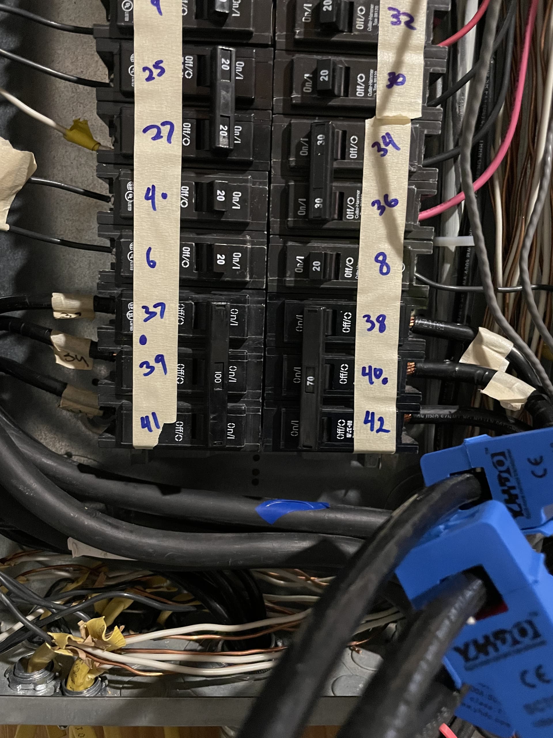
Below is the main building’s sub panel (Panel B), which is powered by the breakers above, 37,39, and 41. From this sub panel there is another one run out to our garage.
I took a bit of time to reconfigure the Phases and believe I have it corrected now. I had to inverse my Phase A, and from there was able to get them all making much more sense. I then tried to see if I could make sense on my own of how the phases run through the panel. I found that breaker positions (not as labeled), 30, 36, and I am mostly certain also 25 are all Phase A. Phase B is on 26, Phase C is through 15, 16, 28, and 33. I hope this makes more sense to you than me!
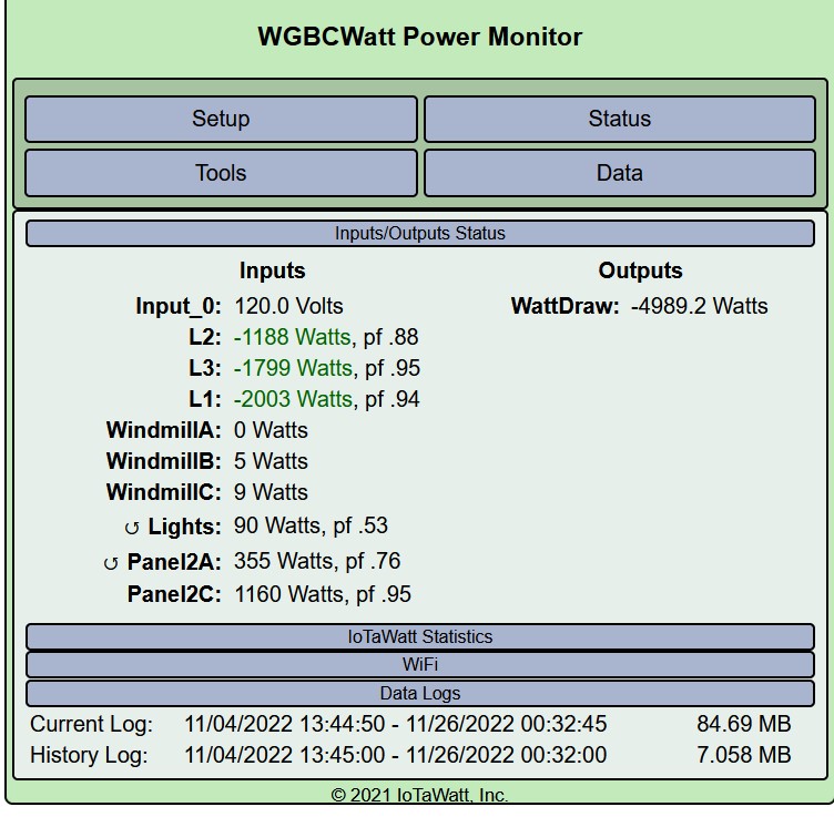
Another bit of real confusion is on the 70A breaker that goes to the turbine panel, the top most wire is not seeing any draw in iotawatt. No clue why at all. The 2nd and 3rd lines do however. Disregard the L1-3 negative numbers as this screenshot was taken prior to my correction on the configuration.
First, I’d like you to take a look at this post from the Open Energy Monitor forum regarding counterfeit YHDC CTs. You appear to have them.
I can see more detail now but sorting this out is still going to take some effort.
I want to start by reading the voltage between
The black wire with yellow stripe appears to be the neutral conductor. You can see it connected to the neutral buss and the neutral (white) wires of the Lights, Outlet and surge protector.
The three on the MAIN DISCONNECT are the L1, L2 and L3 to the building.
Of the three that go to the meter, two are connected to the inverter output through the meter.
The meter appears to be in place to measure the Windmill production. I don’t believe it has anything to do with your utility service for two reasons:
It is inside the building where it would be difficult to read.
It does not have a seal on the box.
I question that. The service appears to be 120V/208V (standard three-phase) and the display that you posted says 211 VAC.
I disagree. I’m pretty sure the Windmill feeds back through Panel A. Monitoring that 70A breaker in Panel A should give you the output of the Windmill minus any power used by the lights and 120V outlet.
The Mains CTs look OK. Two of the windmill CTs appear to be those counterfeit mentioned above.
I think that it’s a standard three-phase panel. Lets call your mains L1, L2 and L3 from left to right.
With that pattern, you can install a three position breaker anywhere and get three-phase or a two position anywhere and get 208V.
The windmill only connects to two of the three conductors. If the Lights or Outlet are on that third conductor, you will see some current on that leg when in use.
Your mains phases may be correct, there is a procedure for determining mains phase assignment for derived reference in the docs. I’d advise you understand that and double check.
The Lights may have the wrong phase. When you identify the IoTaWatt phases A, B and C, they may not correspond to the A, B and C on your panel label. IoTaWatt Phase A is always the phase where the VT is plugged in.
Once you identify the IoTaWatt phases corresponding to your L1, L2 and L3 (to distinguish from IoTaWatt’s A, B and C), you can determine the phase of any breaker using the pattern above equating the L1, L2 and L3 to the IoTaWatt A, B and C. Make a chart if it helps.
Most excellent response! Much of that makes sense to me. It is unfortunate about the CT’s I shall be returning them promptly.
I am near certain my phase configuration is correct at this point. I actually had shut down nearly all breakers that were not going to cause significant load spikes. I used a panini maker which pulls a decent bit of power. For reference I began on the outlet my VT is plugged into, breaker labeled “8” towards the bottom of Panel A. At the time, it went from -69.2 to -1300. I then tried wire 35, which is currently in breaker position 15. The reading went from -.1 to -1229. Then I used wire 1, at breaker position 26 and had a reading of -42.3 to 1295.5.
Let me quickly apologize for the odd numbering and references. My panel was a disaster, and its been worked on. Lots of tracing and remapping the panel itself.
I followed through on the configuration steps, and determined 1, 3, and 2 respectively at that point. I am hoping you agree with my solution!
If I were to pickup a second Iotawatt to leave in the turbine shed, you mentioned it doesn’t need wifi. However, would there be a way to track by date or whatnot to compare to the usage i get on the mains from my building, and then net them against each other? Even for a mostly accurate reading? Honestly, I may need a 3rd, or even 4th one soon to track the usage for some of my production side so I can use them to even more properly cost out my utility expense for production.
If what I described works out as true, you really don’t need anything in the turbine shed. The CTs in the main panel feed will give you the wind production. You also have the meter in the windshed that can be used to validate the IoTaWatt measurements.
Please post the results when you get good CTs on the wind feed. After that, I’ll describe how to validate against the wind meter, inverter and your mains against the utility meter. Also, how to integrate import/export.
Hope the all is well. Slight snag in my setup due to weather and holidays. I did finally get 95% of my wiring done inside of my panel and it is ready for more monitors, but that is in due time. I had tried to do a little research in my downtime so I have some questions and can hope to provide some more clarity and ask more questions to provide confusion!
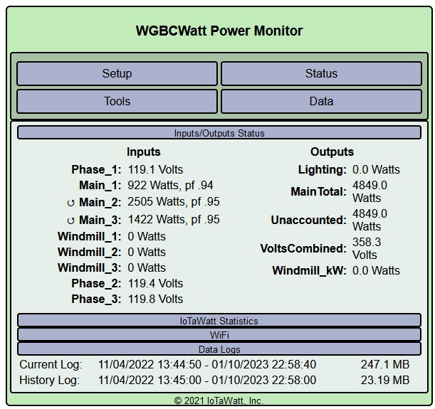
I have since the last time, installed 3 additional outlets off of my box to provide the proper referencing for the VT’s on each leg, and have tested them to know which is which. When I look at the status, I am seeing that it appears 2 of the CT’s on the mains are not facing the proper direction, but physically looking at them I can confirm they are all the same orientation. Just to clarify better, I am no longer using the derived three phase reading.
You will see also from the screen shot that I have 0 watts on the windmill CT’s. This is because after the windmill starts up I am getting a high pitch resonating sound, almost to that of a pump that increases in pitch as you increase its hertz. It is a constant sound, but not one I remember in the past.
We had a very rough winter storm with bad winds and I don’t know if it is a result of that. That said, I did move the proper CT’s I had to it, and had only positive results except for one leg that read near 0. I imagine that one may have been specifically for a light and an outlet that are out there and not used for anything else.
That all said, do you think it is still back-feeding into my panel? I am not trying to undermine your assumptions but they also are only as good as info I can get you. My electrician seems to think if the turbine was indeed feeding back, there would be a pretty bad blow in the panel itself. I however cannot vouch to this accuracy as he is not a windmill specialist. I hope to get it back on and see why it is indeed producing the humming noise but until I can identify why it is doing it, I don’t feel safe leaving it as is. Hope this helps shed a little more light on things!
I see nearly the same voltage on all three, so derived should have been plenty accurate. If all of the CTs are oriented the same way, you probably have the polarity of the VTs reversed. Rather than reverse the CTs, try reversing the associated VTs. You can do that physically by reversing in the socket, or you can check the reverse box in the VT setup.
Yes.
The turbine feeds the inverter. The inverter produces 208V single-phase output that feeds into two of the three phases going to the shed. If you ever get the windmill going again, you can compare the kWh measured by the IoTaWatt to the readings in the meter in the shed. They should match.