Hello all, first off thanks for the amazing project and helpful support forums, I stumbled across this project while setting up homeassistant energy monitoring and am very impressed!
In the middle of the year before smartguys had stock I impatiently decided I had to have one so started down the homebrew route. I’ve done plenty perfboard esp32/8266 projects but this is one of my first SMT projects.
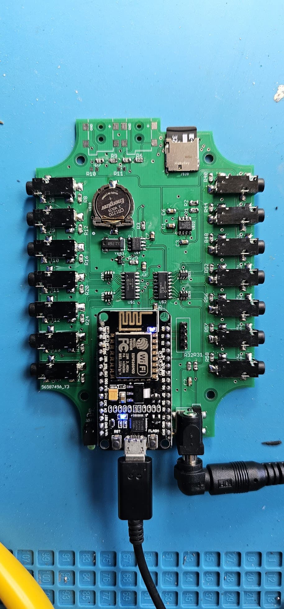
I built 2x iotawatt v5.0 using boards printed @ jlcpcb and parts list from Building Own Version - #2 by overeasy ordered from digikey. I also ordered 2 x sct013 from here
To my delight on powering up wifi, sd card, rtc, webserver etc all work perfectly in both, and powertech MP3027 VT is reading stable 240v 50hz as expected (aus)
Trouble is none of the inputs on either board appear to read any current when clipped around lamp/heater/psu cord etc and connected to any 3.5mm jack and selected as input channel.
Thinking perhaps the cheap cts may be the issue I ordered solid core HWCT04 and spliced to cat6 twisted pair to 3.5mm jack as discussed on this forum but still no readings. I’ve been keeping an eye on smartguys but they’re long term out of stock of their CT clamps - any better sources?
I’m sure it’s an issue with my config or soldering but have tried to check and fix dodgy looking solder joints, and traced connections between components vs schematic with continuity tester on multimeter. I made the second board thinking unlikely to make the same error twice but seems I’m unusually gifted in the error department!
Seeking guidance from you experts on where I should focus my attention given above, and any further troubleshooting suggested to identify and rectify the problem to get these great boards working!
The fact the VT is working makes me think with my limited knowledge that the serial connection to mcp3208, vref, and acbias side of lm358 must be working? maybe the other side of the opamp as seems common to all channels?
Appreciate any and all input, can provide more photos, logs etc if required
Thanks again for an amazing project & community.