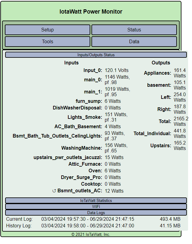
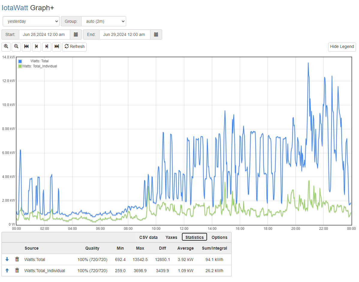
I was able to finally install iottawatt and have been running it for some months now. i calculate the totals Watts for the 2 mains and it is 99% close to the meter reading.
If i calculate the total Watts for all the breakers and try to match it to the Mains, i am off by 1/3. The totals are around 3x the totals of the breakers. what am i missing here ?
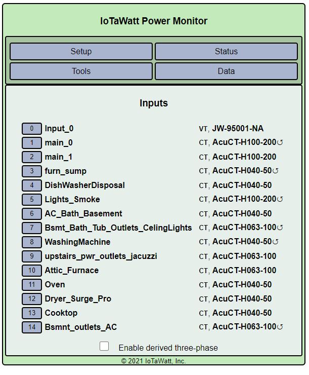
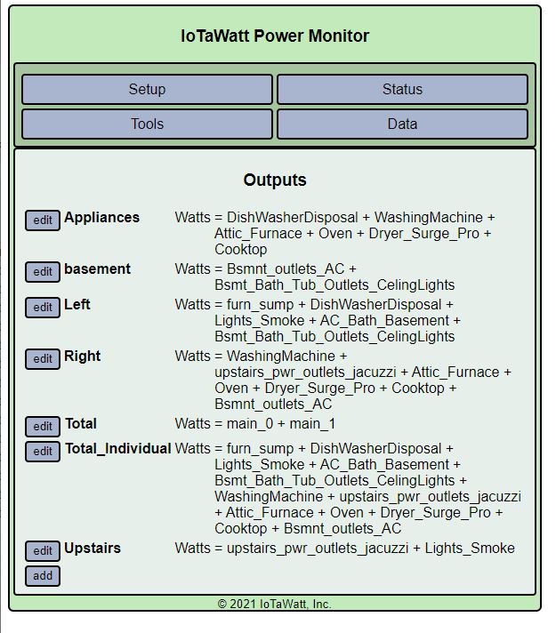
i have added my inputs, outputs, status and a graph showing total of all breakers against total of two mains below
Breaking this down, you have reconciled your mains to an independent standard, so going forward I think it’s safe to say that the mains measurement is correct and the problem is with your individual circuit measurements.
Your diagram suggests that you are combining multiple individual breakers into single inputs. There are several ways to do that, and a lot of opportunity to do it incorrectly. I suspect that is the problem.
Without clear pictures, I’m left to guess what you may have done incorrectly, so here goes:
If you read up on split-phase in the docs, you find that the voltage phase alternates as you go down the rows of your panel. When passing multiple wires through a single CT, you have to pass all of the wires corresponding to one main in one direction, and all of the wires corresponding to the other main in the opposite direction. If you don’t get that right, the incorrect wires subtract from the total rather than add.
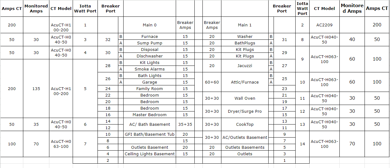
I don’t want to get into any specifics referencing your chart because I don’t believe the Breaker Port numbers are useful as some refer to 120V breakers and some refer to 240V breakers. I’ve not seen a panel where the manufacturer labels some of the slots individually and some collectively.
One simple way to tell which main corresponds to each of the wires is to check the voltage between the main breaker and the individual breaker. If it is zero, then the individual corresponds to that main. If it is 240V the individual breaker corresponds to the other main.
You also have some 240V breakers. In particular you have the Wall-Oven, Dryer, AC/Bath Basement and Cooktop as individual 240V loads. Review the various approaches in the docs to handling those determining if they are two-wire or three-wire.
Hi, I am visiting this again and had another question since i have not been able to fix the issue. The left side of the breaker is main 0 and right side is main 1. Am i wrong in this statement? if i am write then the statement you made " When passing multiple wires through a single CT, you have to pass all of the wites corresponding to one main in one direction, and all of the wires corresponding to the other main in the opposite direction" wouldn’t matter ?
from my diagram up there. breaker port 2/4/6/8 are all on same main and if i put the same CT around them then the number should be correct ? Sorry if i sound silly.
trying to understand this since last time an electrician charged me 150$ just to replace a breaker and i paid 300$ to install the CT (which are not correct it seems)
The way most panels are built, the phase alternates for each row, not each column. Without seeing a picture, I would guess that breaker ports 1,2,5,6,9,10,13,14,17,18,21,22,25,26,29,30 are on one phase and 3,4,7,8,11,12,15,16,19,20,23,24,27,28,31,32 are on the other.
So no, 2,4,6,and 8 would not be the same phase. 2 and 6 would be one phase 4 and 8 would be the other. With all of the wires going the same way, that CT would be showing 2 + 6 - 4 - 8.
So i gathered courage and took the Breakerbox cover off. here is what i saw. still deciphering what i see but wanted to share the photos.
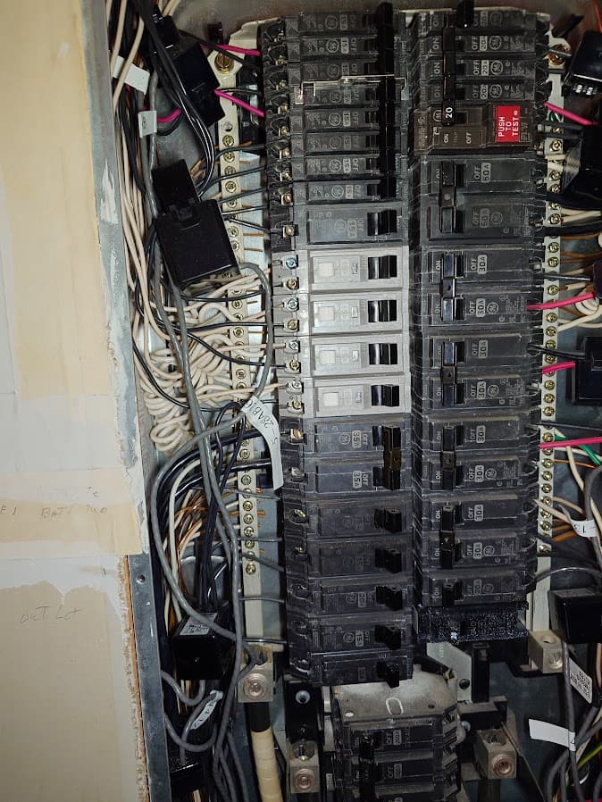
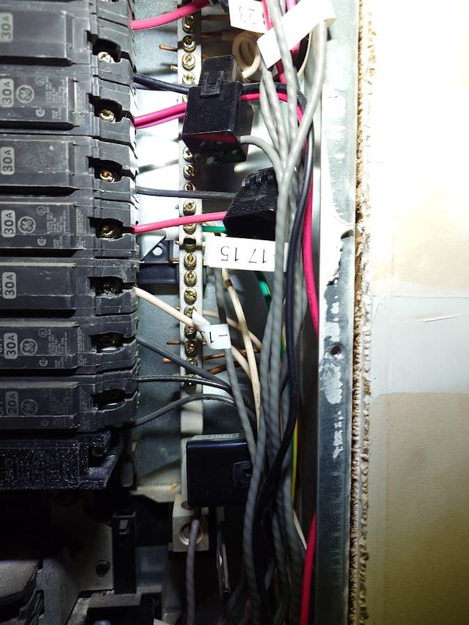
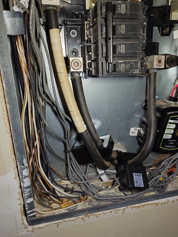
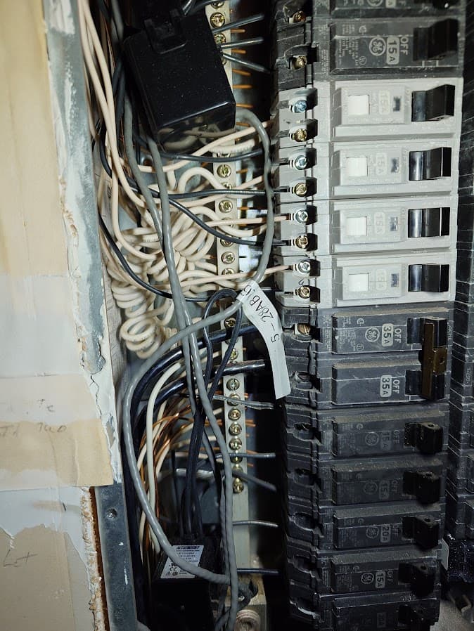
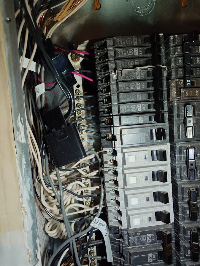
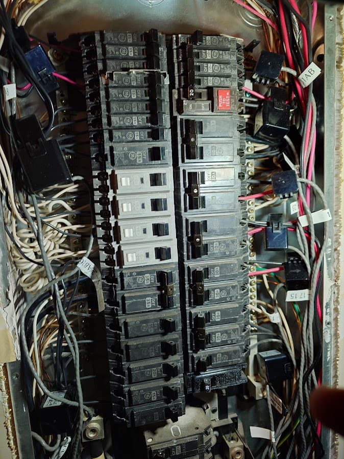
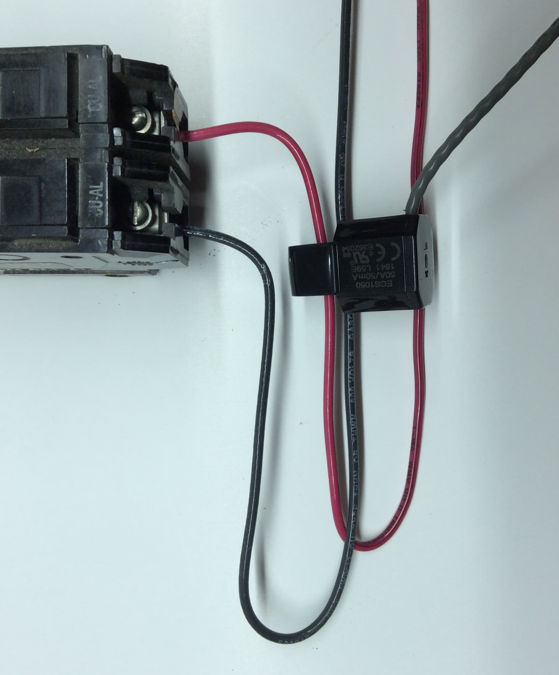
Looking at the pictures provided, it sure looks like many of the CTs with two wires going through them are canceling each other out. Any two adjoining breakers on one side of the panel will need to have one wire reversed when going through the CT. I am not seeing that in your photos.
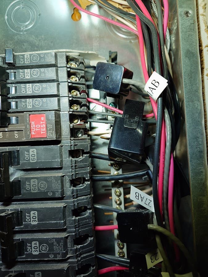
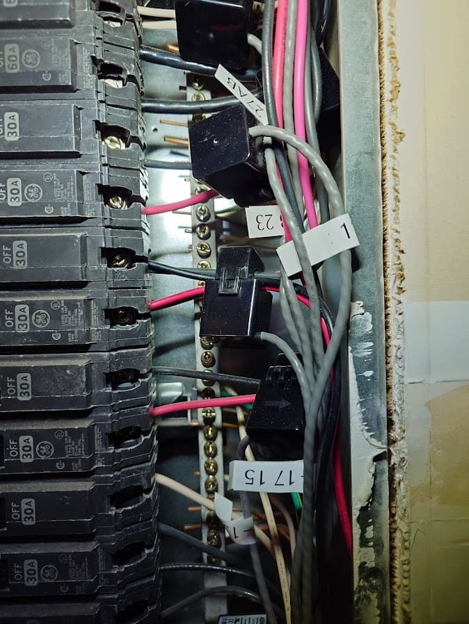
Digging in a little deeper…
These spacesaving breakers are squeezing two breakers into the space normally used by a single breaker. Thus, the following CTs are wired fine, as each narrow pair of breakers are on the same phase.
However, these normal width adjoining breakers breakers are each on a different phase. Thus, they are cancelling each other out. One of the wires in each of these CT needs to be reversed.
Also, it appears you are not monitoring many of the circuits in your electrical panel, and thus the total of the individual branch circuit CTs will never match the total of the two MAIN CTs. This is common and completely normal. Most users will choose to monitor circuits that contribute largely to the total consumption of electricity.
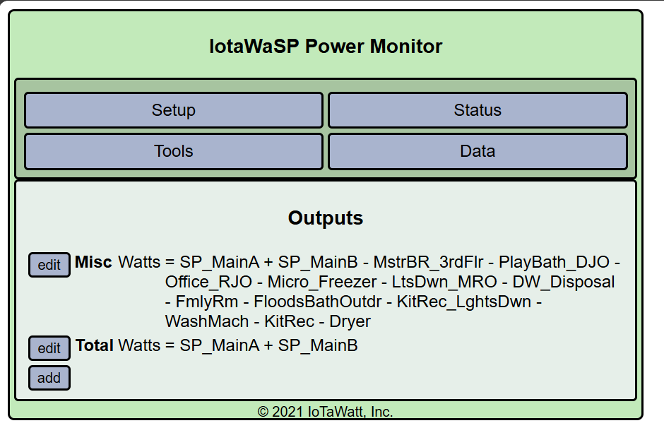
Here is what my SubPanel looks like, where “Misc” refers to a calculated Output of the Total of the 2 Main CTs - the Sum of all of the other CTs. This shows me what the unmonitored circuits are using.
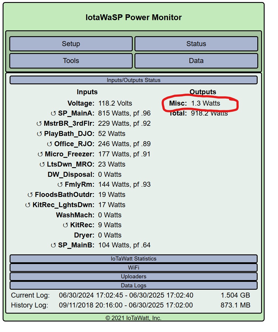
Here is what the two calculated Output values look like in the configuration tool.
1 Like
Taking a little of overeasy and ogiewon’s recent comments and adding in the way my mind works, I would reorder the layout of your table and add an additional column. This might help show the relationship of the phases, breakers, and circuits.
My order would be from left to right
Column A: Breaker Port Number
Column B: Breaker Sub-Port (your A/B for the half height breakers)
Column C: Phase (new - maybe use L1 & L2 since you are using A & B already)
Column D: Breaker Size
Column E: Circuit Description/Usage/Devices
Column F: Monitored Amps
Column G: CT Amps
Column H: CT Model
Column I: IotaWatt Port
Column J: Blank/Empty
Column K: IotaWatt Port
Column L: CT Model
Column M: CT Amps
Column N: Monitored Amps
Column O: Circuit Description/Usage/Devices
Column P: Breaker Size
Column Q: Phase
Column R: Breaker Sub-Port
Column S: Breaker Port Number
Disclaimer…I am not an electrician so the following is very suspect information. You have been warned. ![]()
Also, I don’t think that your Jacuzzi breaker is really split into an A & B. Yes, it has two wires connected, but that looks like a GFI breaker and the second (white) wire is for the neutral and you will just want to monitor the hot (black) wire.
The top Attic/Furnace breaker (25) probably doesn’t have an A and B as it is a full/standard height breaker.
Here is a bad attempt of a brief sample table for the upper right breaker/circuits.
| Col O: Circuit Description | Col P: Breaker Size | Col Q: Phase | Col R: Breaker Sub-Port | Col S: Breaker Port Number |
|---|---|---|---|---|
| Washer | 20 | L2 | A | 31 |
| BathPlugs | 20 | L2 | B | 31 |
| Kit Plugs | 20 | L1 | A | 29 |
| Kit Plugs | 20 | L1 | B | 29 |
| Jacuzzi | 20 | L2 | 27 | |
| Attic/Furnace | 60 | L1 | 25 | |
| Attic/Furnace | 60 | L2 | 23 |
1 Like
Yes, for two adjoining standard width breakers, that looks correct to me.
Thanks, i will update my table since that would definitely help.
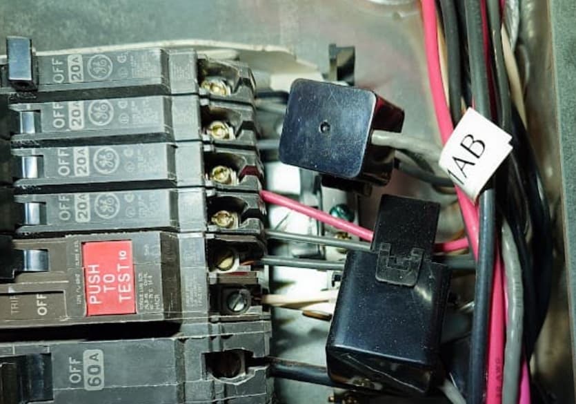
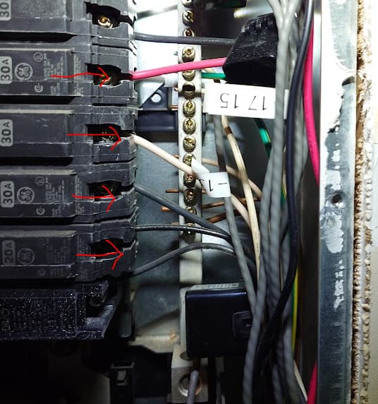
one more question, look a the photo attached with red arrows. All those are individual wires to each breaker so i can clump them together and pass them through the CT (lets say 200Amp) on and it should be fine ?
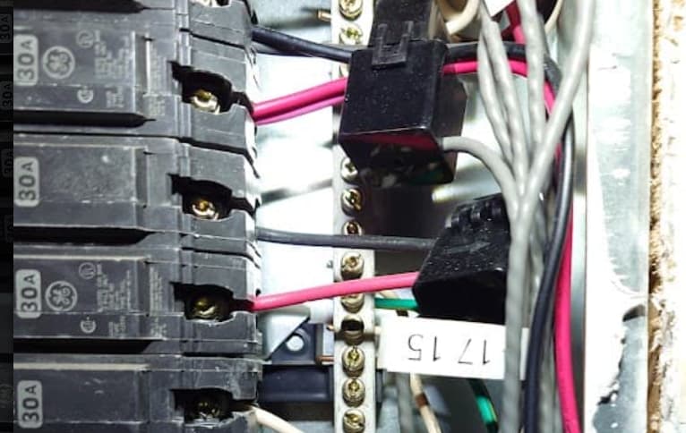
for the blue arrow photo
again, i would use the black and white (reverse) for calculating the total ?
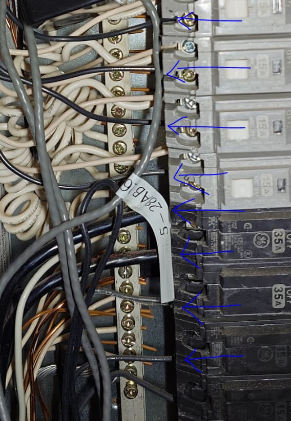
For bottom picture with the four “standard sized” “bedroom” (gray) breakers in ports 16, 18, 20 and 22 as has been pointed out previously, watch which phase the breaker is on and route the wire through the CT in proper direction. Are they GFI as well? Can’t tell in pic, but looks like they have two wires connected to each. If they are, the hot (black) wires for port 16 and 20 go in one direction and the hot/black wires for ports 18 and 22 are routed through the CT in the opposite direction.
For breaker port 12 and 14, see the last paragraph in overeasy’s June 30, 2024 post about 240V breakers. For what I think is port 10 that doesn’t look like a GFI breaker as you have it labeled in the original table posting.