Two systems setup: a single phase and a 3 phase

So, I’m ready to punch the order button, just want to make sure I have everything right first. Or at least, my order makes sense with the information I have anyway.

I’m actually ordering two systems, one for my apartment, single phase 240v, and one for dad’s place as a Xmas present, 3 phase, 240v with solar and a three phase car charger.

My setup

This should be pretty straightforward:


I want to monitor each circuit individually, and will be adding a new circuit next year for a water heater (I’m paying 90 bucks a quarter in connection fees for 3 bucks of gas, can’t wait for the end of that).
So one 100A CT for the main in, and seven 50A CTs for each of the other circuits should be right, correct?
Then one VT and the USB power on a GPO from any of the circuits should give the right readings to calculate everything? From what I understand in the docs, there is no need to measure neutral lines in a single phase, at least, right?
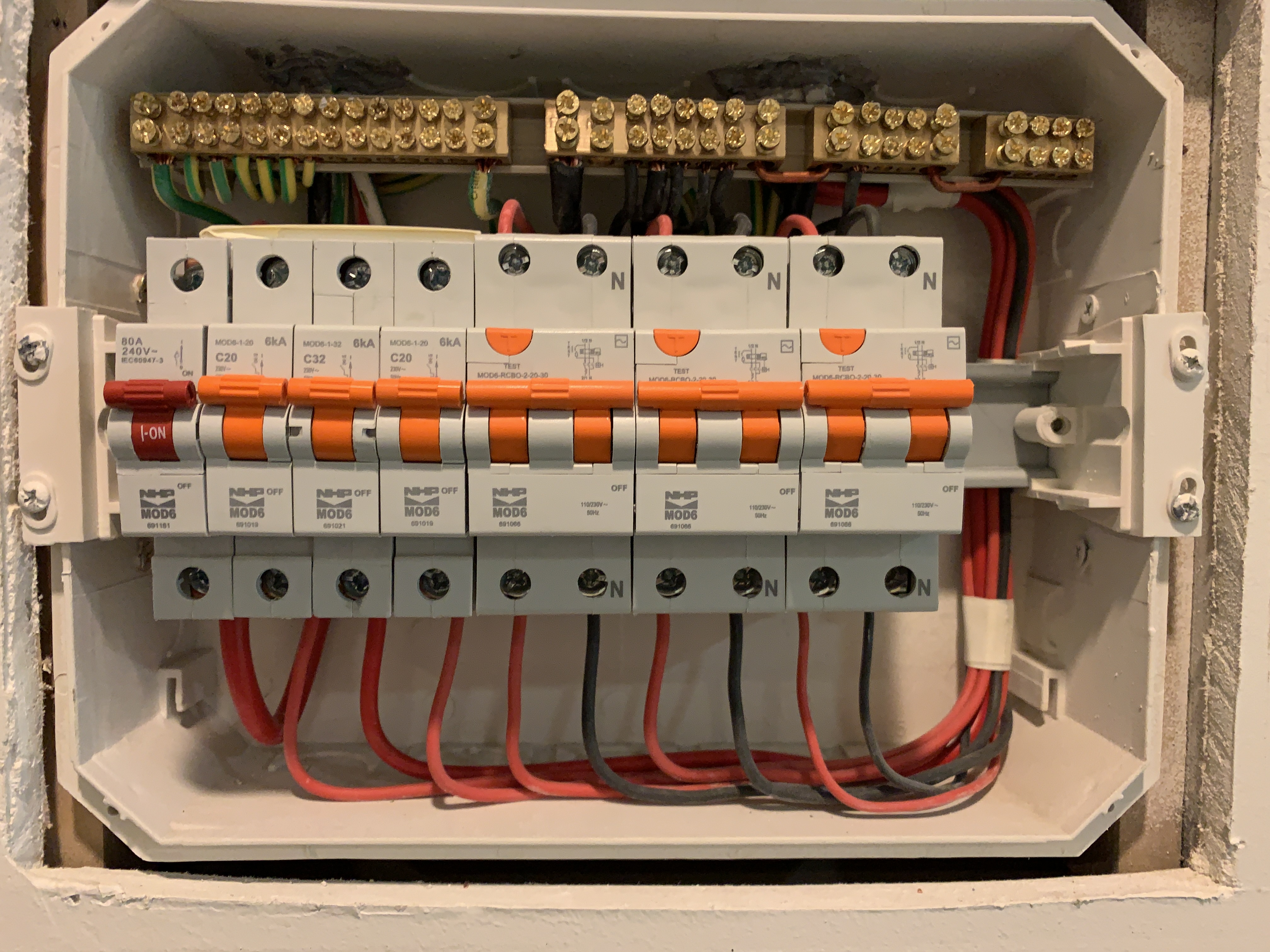
Dads setup


So would I need a CT for each line through the mains breaker? (One per phase)


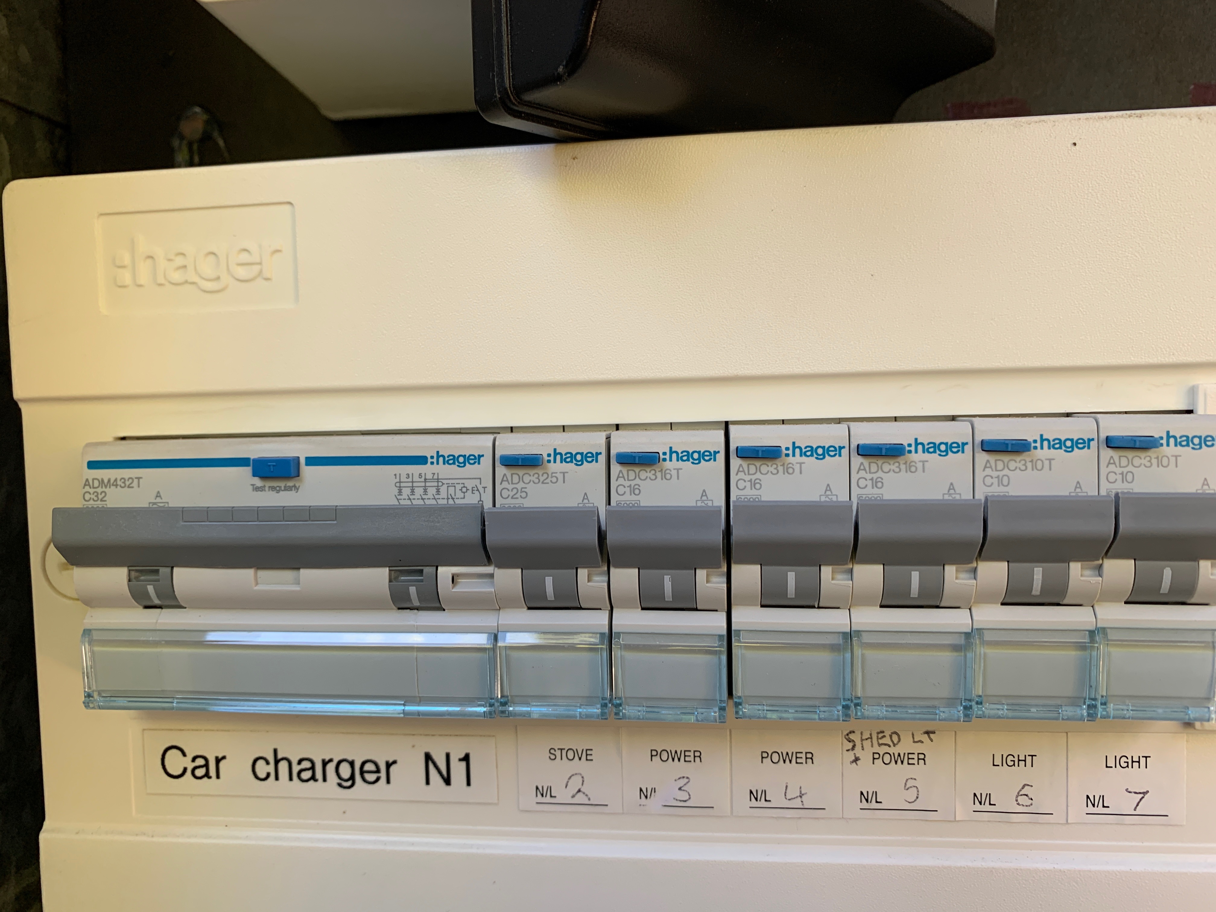
The car charger breaker has one live line for each phase, plus a neutral line. Would I put a 50A breaker just on each live, or on the neutral too?
The I wouldn’t bother measure the lights or the “shed light + power”, as it’s all efficient lighting and the “shed power” is just running a motion activated outdoor light as well, so a 50A CT on the stove and one for each of the remaining 2 “power” circuits.


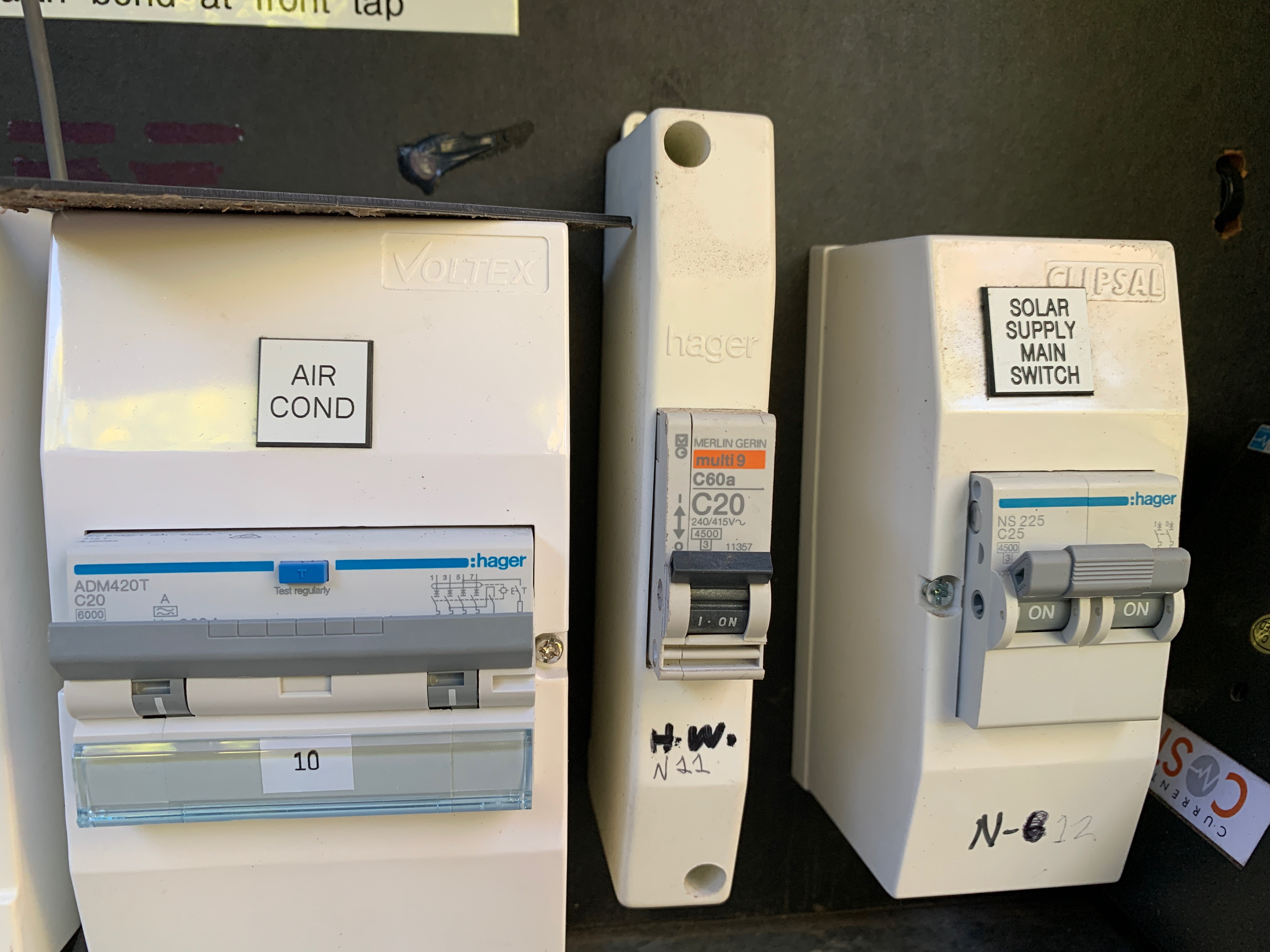
I remember reading on someone else’s setup that a solar inverter will have two lines, but you only need to measure one since they’re both the same circuit, so one 50A CT for the solar?
And given power coming in from solar is from a different source than the mains, do I need a VT to measure its voltage? I didn’t see anything in the docs but there wasn’t a lot on measuring solar specifically.
And the AC is 3 phase, so same question as the car charger, three 50A CTs just on the live lines, or four to include the neutral?

Aaaaand my math puts me at a sticking spot, now that I’ve written it down.
IoTaWatt has a 3 ports for VTs and 12 remaining for CTs
Best case:
3x 100A CTs for main in
3x 50A CTs for car charger
3x 50A CTs for A/C
1x 50A CT for stove
1x 50A CT for Power 1
1x 50A CT for Power 2
And we run out of CTs for solar(1x), let alone if the neutrals need CTs (2x)


Don’t support that ESP32 version with the breakout board is coming soon enough to give a pre-order for Xmas? :laughing:

If anyone sees any shortcuts that can be taken to make this fit in a single IoTaWatt, I’d love to know how! Could I combine the two power circuits into a single CT if they are the same phase, for example?
Otherwise I guess I’d need 2 IoTaWatts for dad, and have one measure two phases and the second measure the remaining phase and the solar? On the upside, everything would be exactly measured, no inferring anything… :stuck_out_tongue:

Thanks in advance for any insight!

Hi Tony,

I’m guessing this is for the land down-under, so Christmas is probably not going to work unless You can get Santa to do what the post office cannot.

Your apartment setup look good. There is no need to measure neutrals, although for any circuit, you could install the CT on either the line or neutral (reversing if on the neutral).

Your dad’s three-phase is pretty straightforward, as three-phase goes. The solar appears to be single phase. If that’s the case, then yes, you only need a CT on one of the lines (again line or neutral).

So that comes to 13 CTs with the solar. You can set this up with one VT using derived reference. It’s not as exact as direct reference with three VTs, but it’s usually very close. I recommend you try derived.

You can combine circuits that are on the same phase. With a little research, you also may be able to monitor the AC and/or car charger with fewer CTs. The AC load is predominantly a motor, which should load each phase equally. One of the phases may also be drawing additional power for controls, so when you have all three monitored you may find that two phases are the same. If that’s the case, you can repurpose one of the CTs elsewhere and create an output that adds the remaining equal phase x2.

Same approach for the car charger.

Once again Bob, your wealth of knowledge proper blows me away. That you can look at what info I had there and just drop down two different working solutions so easily is awesome.

Unfortunately, for now, I feel like I’ve wasted your time, sorry! :anguished:
A branch got blown off a gum the other day and damaged the casing around the mains enough that he has to replace the whole box, so he’s gonna completely redo everything in there and move it to a more convenient point around the house for when he gets battery packs done.
In doing so, he’s gonna get some of the circuits in the house broken up a little more so something tripping the breaker in one part of the house doesn’t shut off things in completely other parts of the house (cause apparently that’s a problem…?)

I know he’s been wanting to move it all a bit for a long time anyway, it’s been a bit in the way since the solar inverter got put next to it, since it hangs off the wall in a walkway, so I guess this is the excuse he needed to justify the scale of work.

But it means I have no idea anymore what layout of CTs we’ll be needing in the end, so I guess this becomes a Father’s Day or birthday present anyway.

I’ve ordered the one for me anyway, looking forward to getting it set up. I guess a plus side is that I’ll get some hands on time with one before introducing dad to it, so I’ll be better able to help integrate it into his existing power monitoring software :slight_smile:

Can’t wait till it gets here to get it running! Thanks again for all your advice! Once his switchboard is redone I’ll order what I need for him is it’s pretty similar, or I’ll post new photos if it’s drastically changed. But I think what you’ve explained here has increased my understanding enough to properly figure it out myself next time :blush:

1 Like

Ok it’s been a while, but a thought occurred to me just the last day or so.

I just ordered the kit for mine (the single phase system), and aim to be installing it in a in-wall unit not unlike the circuit breakers pictured above. I have the measurements for the IoTaWatt itself, but I’ve just realised that (obviously) the CT connections add length and width when in operation.

Don’t suppose you have a ballpark figure for how long and wide it all is when you have CTs, a USB power cable and a VT line connected, so I don’t end up getting a unit that has the cables pressed up against the sides at harsh angles? Don’t really want to have to replacement due to an excess of strain relief :joy:

I got the 50A and 100A CTs from your store, if that helps.

And if anyone is wondering about holiday shipping times to Australia, USPS picked it all up on Dec 15th and the last tracking update was on Jan 4th, waiting at JFK airport New York, for a flight to Aus.
Hope the shipping lanes clear up soon for everyone :sob::grinning_face_with_smiling_eyes: