I think I’ve got enough to make a pass at this, with the reservation that a photo of the IoTaWatt CTs may change my understanding.
High Sunshine
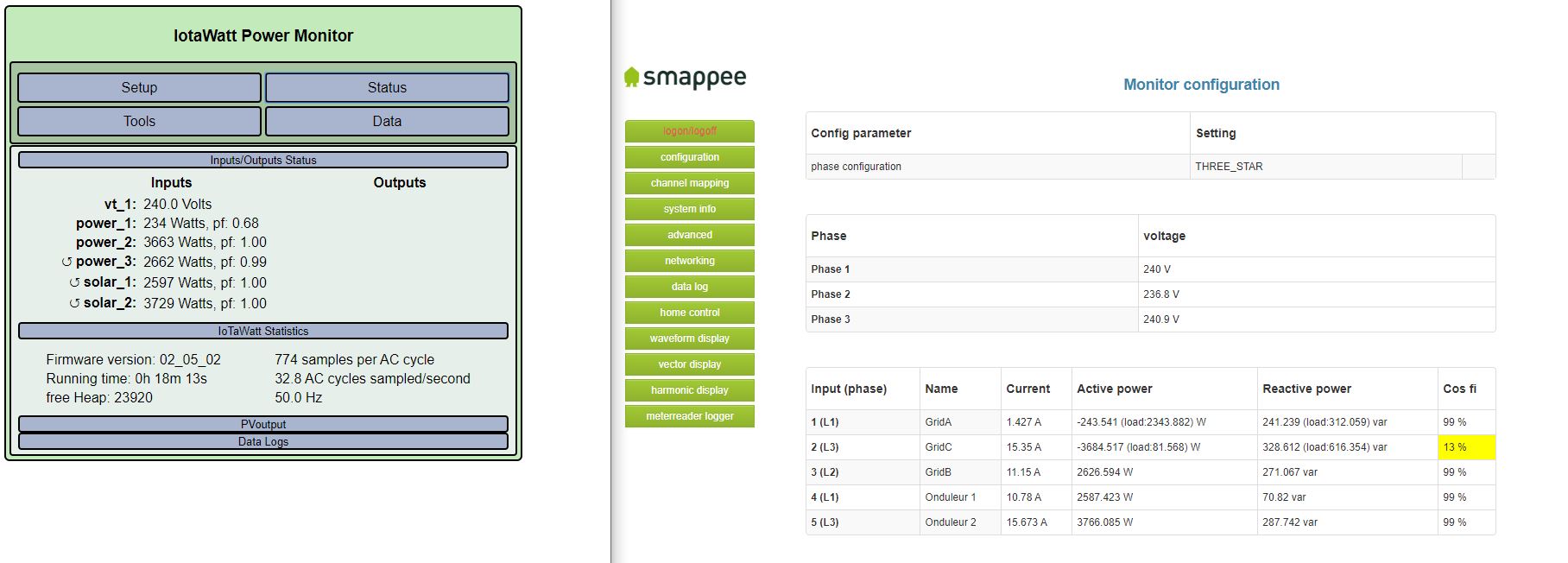
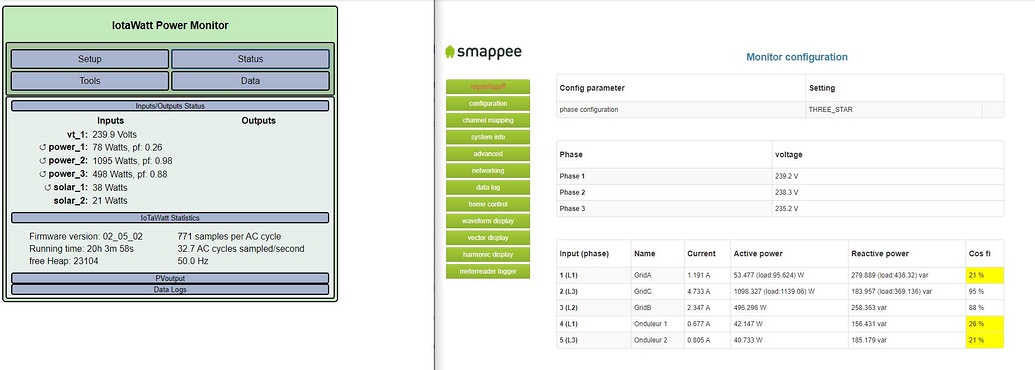
Lets take a look at this set of screenshots:
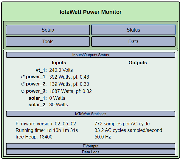
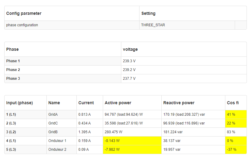
What jumps right out is that everywhere the IoTaWatt sees negative power, marked with a ↺, the Smappee sees the opposite, and when IoTaWatt sees positive power, the Smappee shows negative power.
In a simple system, this is no problem. IoTaWatt simply makes the negative positive and everything works out. When there is solar generation flowing out through the mains, it’s a problem. The signs must be correct and they must be allowed.
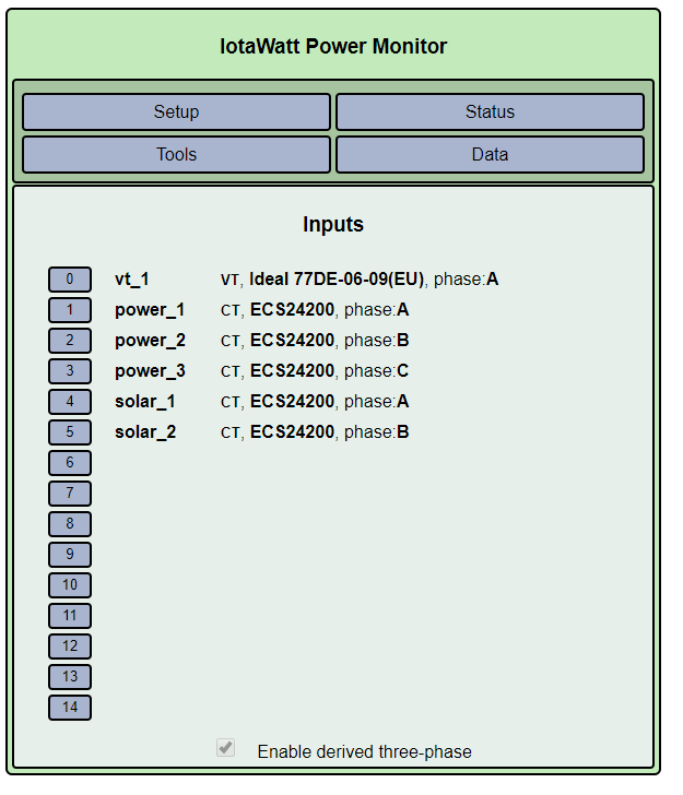
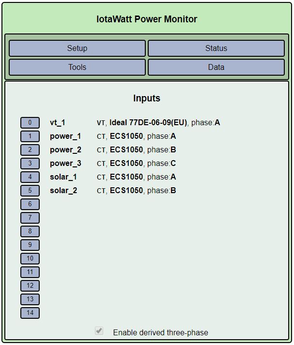
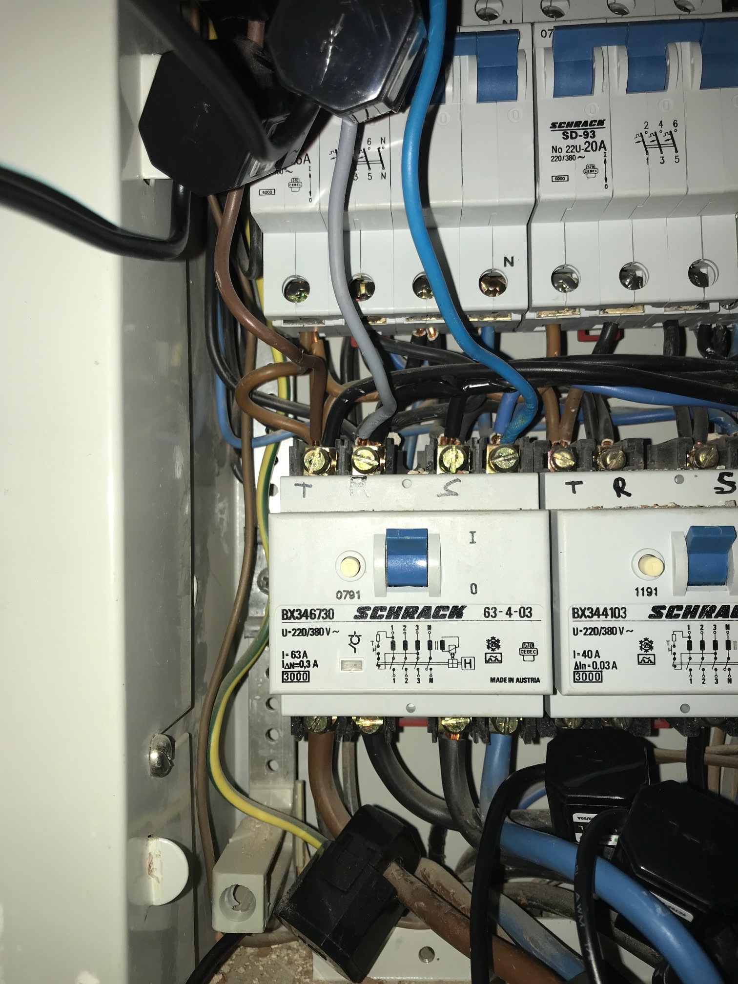
By the documentation I was able to find on the Smappee, the voltage references are hardwired. There is a common neutral and individual “hot” conductors for each phase, so polarity is known. In this case IoTaWatt is using a VT with a standard two prong Euro plug. It can be inserted either way. The odds of the polarity correctly matching the CTs is 50-50. You guessed it, it’s 180° out of phase.
There are two ways to correct this:
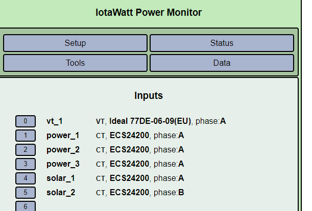
- Physically turn the VT 180° in it’s socket
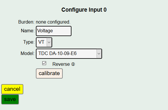
- Check the “reverse” box in the VT configuration as here:
Once this is done, there should only be negative values in the power_1 and power_2 mains when the inverters are producing excess power. (There is a negative issue with the inverters that I’ll get into later).
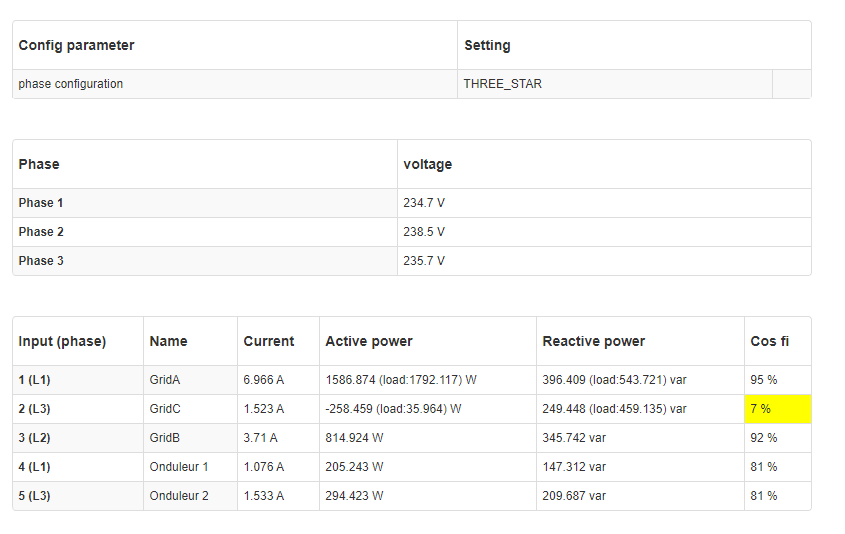
At this time I want to point out that the Smappee is flagging the power factor of input 2 as .13 . Most of the other PF values are reconcilable, but I can’t figure out why it’s doing it here. Computing the apparent power from their numbers I get 3,699 VA. Power factor should then be 3684/3699 = .996. IoTaWatt shows 1.00 (unity) which is what I would expect with a solar inverter providing all of the power that is being exported.
These PF anomalies were causing my initial questioning of Smappee. I think they are incorrect, but they may have some other justification for it. Regardless, when they are ignored, the actual power values appear to be close.
The last thing to note about this set of displays is how the IoTaWatt and Smappee compare in Active Power values. First note a little confusion in that input 2 for both units uses what is Phase 3 in the Smappee (240.9V), and input 3 uses Phase 2 (236.8V)
IoTaWatt is using derived voltage reference, which means it uses the Phase 1 voltage (240V) for all three phases and numerically shifts the phase. So it’s results will differ proportional to the reference voltage difference.
power_2: 3663 Watts * (240.9V / 240V) = 3676 Watts
power_3: 2662 Watts * (236.8V / 240V) = 2627 Watts
So the three mains compare as:
power_1: 234 vs 244 = 4.1% difference
power_2: 3676 vs 3685 = 0.3% difference
power_3: 2627 vs 2627 = no difference
power_1 is the net difference between significant consumption and generation, so unless the two values were somehow taken at the exact same moment, I would not put a lot of emphasis on the power_1 difference.
I’d like to point out here, for the benefit of others reading this, that you can add two additional VTs to IoTaWatt to get direct voltage reference on all three phases.
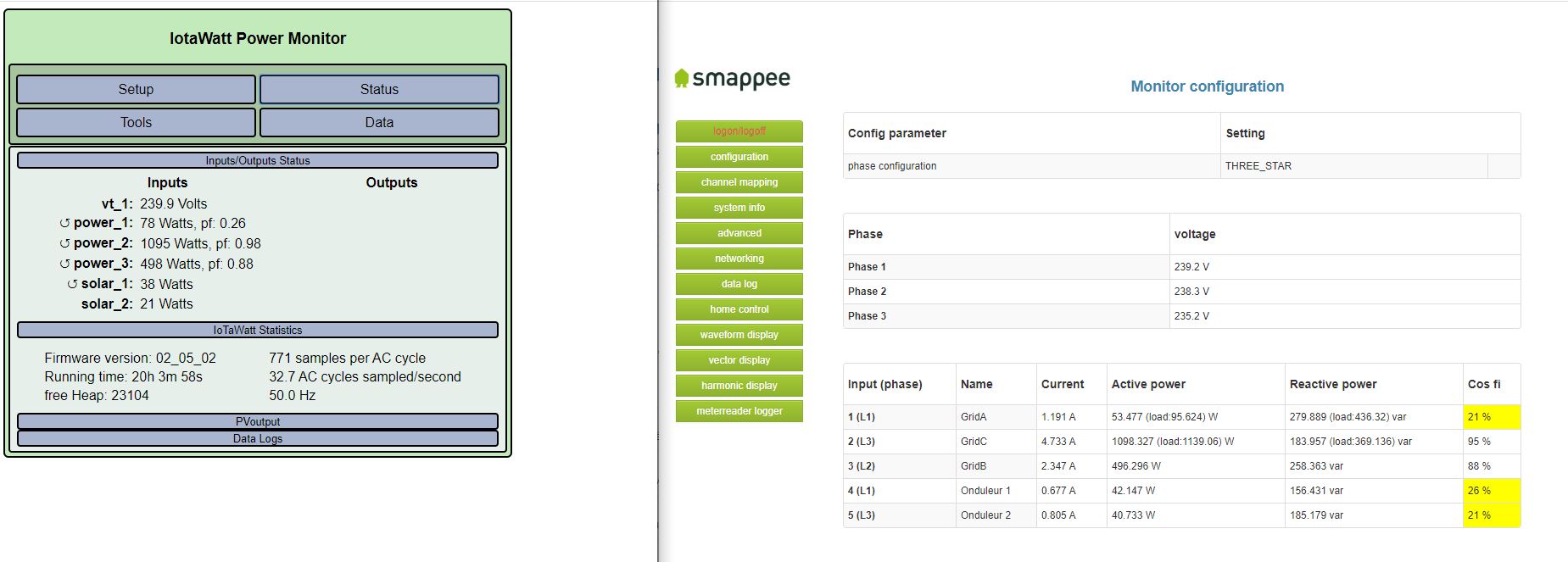
Low Sunshine
Now moving on to the second set of displays with “low sunshine”.
First let me say that it’s not clear exactly what’s going on with the solar. The running time is 20 hours after the previous “high sunshine” displays, so it’s 4 hours earlier in the day. Presumably early morning. The inverter outputs are ambiguous here.
Recall the ↺ symbol that we looked at in the mains. We see it here on the solar_1 input, but remember that everything is backwards due to the 180↺ VT orientation, so actually, IoTaWatt is saying that solar_2 is showing backwards power. This is common with inverters. They consume power while in standby mode, and 21 Watts is fairly typical.
The other inverter does appear to be producing power to the tune of 38 watts. I speculate this is due to PV panel orientation being more easterly on the solar_1 array.
The Smappee doesn’t appear to differentiate between generation and consumption of the inverters. Both appear positive. This could simply be that the two screenshots were taken at different times and the second inverter is now producing, or it could be that the Smappee gets it right but doesn’t display the negative number. It’s a third order issue at best, so moving on:
In addition to the sign, there is also a difference in magnitude between the IoTaWatt and Smappee with respect to the inverter out here. Again this could simply be the result of simply taking the screenshots at different times - even a few minutes will show significant changes during the early morning ramp-up. Another possibility is that the two units simply have different accuracy when the current is 160mA. Which is the more accurate isn’t really that important because if you look at the “high sunshine” above, with the solar_2 adjusted for the derived voltage, the two inverters are within 0.4% difference between the IoTaWatt and Smappee.
PVoutput
Given the above reconciliation of IoTaWatt and Smappee, it’s reasonable to expect pretty accurate results with PVoutput. Unfortunately, the configuration shown in a previous post will not produce that. There are several ways that solar output can be introduced, and now I have enough information to get into that.
First, I’d recommend that you read tyhe documentation at PVoutput — IoTaWatt 02_03_20 documentation
It uses the North American split-phase case, but the principles are the same with respect to how the consumption is specified. Here is what you posted:
So here the generation is pretty straightforward, and you seem to be satisfied with the result on PVoutput. The difference between the two is less than 1% which isn’t bad for two inverters and 5 minute resolution accumulation in PVoutput. The IoTaWatt probably has a more accurate value, and I need top point out here that if both inverters are each using 20W on standby, that’s 0.64kWh of standby power consumed by the inverters over 16 hours, which is
about 5%-6% of your total generation. Food for thought.
Your consumption calculation is wrong on two fronts:
-
Because the inputs 1 and 2 are not allowing negative values, your exported power is being treated as consumption.
-
Because the generated power is not included in the calculation, the generated power being used is not included in consumption except any portion that is being exported is being incorrectly included as above.
So what to do about it.
-
As previously instructed, insure that power_1 and power_2 have the “allow negative values” checked in the inputs setup.
-
Change your consumption script to be:
Watts = ((power_1 + solar_1) max 0) + ((power_2 + solar_2) max 0) + power_3
-
If you want to eliminate the inverter standby power from your generation, check the “allow negative power” for the inverters and change generation to:
Watts = (solar_1 max 0) + (solar_2 max 0)
Note that all of these changes are based on the expectation that you will reverse the VT as explained in the beginning. None of this will work properly if that isn’t done.
Let me know how you make out, and could you tell me the name of your PVoutput station so I can see that as well.