Understanding data in new install - EV charger counted twice in mains?

I have a standard North American 100 amp 240v split phase service. I have installed these two 100 amp AcuCT-H063-100 CTs on the two phases

I have a couple of unexpected things showing up in IotaWatt now:

  1. Mains_1 shows it should be reversed (and indeed shows negative Watt values when it is not), despite clearly being installed in the same orientation as Mains_2. Mains_2 reports correctly without being reversed. Is it possible one of these CTs is labeled incorrectly?

  2. From the image below, I see the car charger jump to 16 amps, (which I expect), but I also see both Mains_1 and Mains_2 jump by 16 amps, so when I total the usage it shows as if the car charger is using 32 amps, despite both the car, and the CT monitor on the car charger reporting 16 amps.


    Is it expected that the total would be 32 amps when the car charger is drawing 16 amps for some reason that I’m missing? Or are my mains CTs somehow reporting incorrectly? Or something else I’m missing?

More context on my use case:
My goal is to replace all my gas appliances with Electric appliances, but with 100 amp service, I’m pushing the boundaries. I want to use data from IotaWatt fed into Home Assistant to enable load shedding - for example if the total usage is above 70 amps, disable the car charger, turn off the AC, turn off the water heater, etc. However, with the car charger usage showing double I’m concerned about the viability of this plan.

Yes, there is something else you are missing. Please post a screenshot of your inputs setup and I’ll try to explain how your split-phase works.

Thanks! Here are my inputs

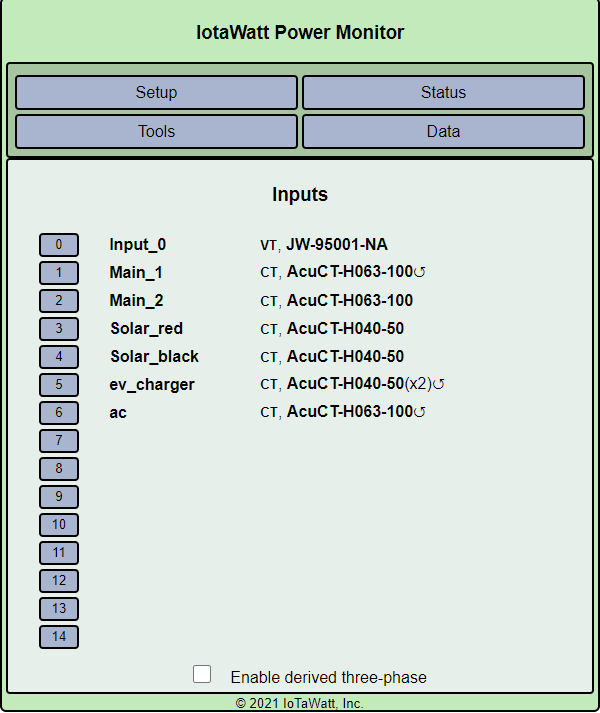
It would be helpful if you read the docs on split-phase power. Specifically, the issue of reversing one of the mains is addressed. I see that you have checked the reverse box for Main_1. The docs will explain why.

Your panel is 100A. That means that each of the hot legs of the panel is limited to a maximum 100A. The potential (voltage), with respect to neutral on each hot leg is 120V.

When you use a 240V load, such as a EV charger, the current moves between the two hot legs for a total of 240V potential. 16A at 240V is 3,840 VA (Volt-Amps). When you use a 120V appliance, such as a refrigerator, the current moves between the corresponding hot leg and neutral.

As you move down your panel rows, the corresponding hot leg alternates. That’s why a double breaker creates a 240V load. The 120V loads are single breakers and the other conductor connects to the neutral bus.

In reality, while the 120V circuits all connect to the neutral bus, only the net difference between the L1 and L2 circuits travels back to the street. The rest conceptually moves seamlessly from L1 loads, to the neutral bus and then through the L2 loads. Effectively creating an aggregate 240V load.

To measure all of this 120V and 240V activity, we break it down into two 120V loads - the L1 and L2. We look at the mains current in each with respect to their 120V potential.

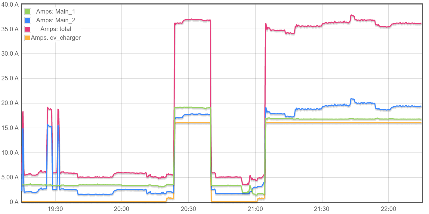
So, when you are using the EV charger, the one CT on the EV circuit is showing 16A, and when you “double” it, you are saying double the 120V reference voltage. You have 16A at 240V or 3,840 VA (Volt-Amperes). Meanwhile, each of the mains is also carrying that same 16A of current, but we are using the 120V reference for them. Each main is using 16A at 120V or 1,920 VA. Together they add up to 3,840 VA.

If you plot Watts, which is a function of current and voltage, you will see that the combined mains increase matches the EV charger load.

Now, applying this to your load shedding algorithm. Your limit is 100A per leg at the Mains. So, you need only look at each individual leg. The sum of the two has no bearing on the problem. You could be overloaded with 120A on L1 and 10A on L2. As a practical matter that wouldn’t happen, but you get the idea.

Now practically speaking, your EV charger is not a big load. Most hot water heaters use more power than that. In fact, unless you have many more big loads, I doubt you could get to 80A (The safe limit) on either leg. Try it. Crank everything up at once and look at the current on the mains.

Another consideration is you solar generation. If properly installed, the breaker should be fartest away from the mains in your panel. This is so that the total load on the panel main buss doesn’t exceed the rating. The grid can only supply 100A because of the mains, but your total load can be 100A plus the current generated by the solar inverter.

Believe it or not, this is a simplification of the situation. Total Amps used by a panel will not necessarily equal the sum of the Amps measured to each load. There is a concept called “reactive power” where current can conceptually be shared between your loads. It all has to do with power factor. Suffice to say that measuring each of the mains is the best practical way to determine total load, and most importantly if your solution is to a non-existing problem.

Thanks for the link to the split phase power docs, that makes sense. I had read through the installation docs, but hadn’t made it down to there - I should have looked there first.

Thank you so much for the thorough write up on the actual load calculations - I’m certainly learning a lot with this project.

This is a proactive project before I install more electrical load that could possibly bring our use up to 80 amps total. I know the car load is not currently large - for an unrelated reason it’s limited to 16 amps, but it can be up to 40 amps (and has a 50 amp breaker). I am planning to replace my gas water heater with an electric one (heatpump, so it will still not be too large), and I want to replace our gas range with an electric one, which will be the other large load. The only way I think we could actually trip the main breaker is if we charged the car, had the AC on, and had the Oven and stovetop for the range on at the same time - which we never do - and if we did would likely be in the middle of the day when we’re producing decent solar anyway. However, I’d rather programmatically ensure that we never do that than just relying on everyone in my house to remember not to do that.

Thanks again for the thorough reply, this is super helpful!

I have a HPWH. I considered (for only a very short period) not adding an additional circuit for it, since I was planning on putting it in series (waterwise) with the existing one. I have my heater set for efficiency mode. The docs say it should never turn the element(s) on. My data says otherwise.

When the top sensor gets below 105°F, it will turn the top element on. It will turn the bottom one on if the average temperature is very cold, like on initial start up.

Mine lasted about 5 years before the compressor lost most of the refrigerant. The new replacement is working fine, but I keep a close eye on it.

I experimented with increasing the tank temperature to 142°F to give it more room, but that actually appears to use more energy. So, expect to have periods of using the 4.5KW for the elements even on efficiency mode. My elements were on for 21 min total over the last week, so probably not a big issue.

It sounds like you have a hybrid water heater, not a pure heat pump water heater. Rheem now has a couple of different “ProTerra Plug-in” heat pump only water heaters that can use either a dedicated 15 amp 120v circuit, or a shared 15 amp 120v circuit. I am planning to run a dedicated circuit to mine, but my panel is packed tightly, and I can’t really afford a 240v circuit, so I’m opting for the dedicated 15 amp 120v plug-in. The load there can still be somewhat large, but that’s why I’m undertaking this project to ensure it doesn’t turn on when I have significant other loads already on in the house.

I do have a hybrid water heater. I also (now) have some data on how well it works in heat pump mode. I suppose it depends on your expectations and water usage pattern.

The heat pump on mine can draw 300-450W, which I suspect is typical of the size heat pumps they use in these units.

I looked up the Rheem one you have. They definitely hide the important information, but I was able to find a data sheet. They say 4200 BTU/hr. Based on a 3x for efficiency this is about 400W, so about the same size as mine. They also say 12 gallons/hour recovery for a 60°F rise (this would be 60° incoming to 120° outgoing).

If your family is small and you all take Navy showers (Navy shower - Wikipedia) it will be fine. If anyone in your family takes long showers (10min or longer) someone is likely to be unhappy.

Since you currently have a gas water heater, you probably have little idea of what it is like to run out of hot water. A regular gas water heater has a recovery rate of 30-40 gallons per hour.

2 gallons/min is a low flow shower head, so 20 gallons of hot water is easy use in a not short shower. A 50 gallon tank can probably handle that for 2 showers with a 20-30 min break in-between. But, the output temp will be lower for the next 4+ hours. This is assuming you do not have a recirculating pump system. If you do, that uses about as much as 2 showers a day on a well insulated system.

I appreciate the concern, but I have done my research.

That’s for the shared circuit heat pump water heater, not the dedicated circuit. The dedicated circuit has 28 gallons/hour recovery for the 40 gallon tank (model number PROPH40 T0 RH120).

1.8 gallons/min is an actual low flow shower head, and that’s what we have. If you use 100% hot water in your shower for 10 minutes that’s 18 gallons. However, of course no one uses 100% hot water in a shower, though because showering in 120-140 degrees is not pleasant, so the usage is more like 10 gallons for a shower. I took an extra long shower this weekend when no one else was home and used a whole 15 gallons of total water, say that’s a generous 80/20 mix of hot/cold and that is 12 gallons of hot water.

In any case, my family is just my wife and me and we will not have kids. We take short showers with several hours in between - she wakes up 2 hours earlier than I do most days, and I usually shower at night anyway. So the only time we ever use more than 12 gallons of hot water in an hour is if one of us takes a bath, and it’s been months if not a year since that happened.

That’s not how water heaters work. Hot water naturally stays at the top with a pretty stark line between the hot at the top and the cold at the bottom, while the cold is warmed up. There’s a very good video on this from technology connections

I found the data sheet for that model and it certainly does have a larger heat pump. It is rated at 12KBTU/hr, so almost 3x the size. That will certainly help. If you have no recirculating pump and little other usage on most days you will likely be fine.

Now the problem will be where are you keeping it and what is the temperature there. If you live in the South and the temperature never gets below 60°F outside and you have it in the garage, it will likely be able to use all 12KBTU without freezing. If you live in Texas and get another cold snap, you might also not have hot water.

As far as tank temperature goes, you are correct about the stratification which tends to keep hot water on top. If you only use 10 gallons or so it works well. As soon as you use about 1/2 the capacity, the temperature drops. I could show you graphs, but not convinced you would believe them. With just under 20 gallons of use this morning the top tank temperature dropped 7°F. That is somewhat noticeable, but probably fine. With back to back showers, the temp drops to under 105°F. That is definitely noticeable.

The real caution I advise is, “what is your plan for dealing with the inevitable heat pump failure”?

This is the reason I got the extended warranty (from Lowes, it was only 5 years, the manufacturer warranty is 10 years but no labor after the 1st year). The extended warranty didn’t pay off, but keeping the original regular water heater certainly did. It allowed me have back up while I figured out my heat pump was slowly losing refrigerant and finally stopped working as a heat pump completely.

It is going to depend on the relative price of gas vs electricity in your area (plus what install costs in your area) as to how quickly it will pay off. I am using about 5-6KWH/day for the HPWH. I suspect your usage might be 1/2-2/3 (2-4KWH/day), since you probably use significantly less hot water then we do.

Do make sure you come back and report your usage and how you like it.

In the same place I keep my current methane water heater - in the garage of my California coast house where the temperature stays between 50-90°F all year

The same as my plan for dealing with the inevitable failure of any appliance: repair or replace it. Just like I did when the methane burning water heater failed at my last house. Your implication that a heat pump is more likely to fail than a gas burner just doesn’t stack up. What is your plan when the heat pump in your refrigerator or A/C fails?

Methane costs money, and electricity is free from my solar panels. But it’s really less about the money than the fact that methane is terrible for the planet and indoor air quality.

You seem confident your heat pump is going to last a long time. I hope for your sake it does. The data I have seen and experienced 1st hand indicate getting even 10 trouble free years from a HPWH is not very likely. I don’t have a big AC, but have had good luck with refrigerator compressors. Small heat pumps (like in dehumidifiers) have been incredibly short lived.

But, you have done a lot of research on the HPWH you have chosen and it looks like it will be more than adequate for your needs. It probably also comes with a 10 year warranty, which is something. In less than 5 years I will know if my 2nd one will last long enough to get past the 10 year warranty of the first one. I keep a much closer eye on it so I will know when it starts degrading and won’t be caught by surprise when it fails more completely.