I idscovered IoTaWatt a few days ago and have been reading many of the forum posts. I was having a bit of trouble understanding how the sampling rate works. As I understand it, only one channel can be sampled at any given moment. So a loop iterates over each channel, sampling one full cycle (1/60th of a second in the US) before moving to the next channel. About 650 VI pairs are collected per full cycle. The real power, apparent power, and power factor are calculated. It takes about 1/2 second to iterate over the 14 channels. The end result, for each channel, you capture 2 of the 60 cycles per second. A data point is logged for each channel every 5 seconds, which consists of the average of the last 10 samples.
Do I have this correct?
My questions are:
Are I and V measured at simultaneously or sequentially?
If I just measure the two legs of the main, would I now capture 15 of the 60 cycles per second per leg? Would the overall accuracy improve relative to a revenue grade meter? Are there any advantages to this?
Which loads are difficult (or less accurate) to measure with a 2 sample per second per channel methodology vs continuous sampling of a channel?
Thanks and feel free to educate me if I’m on the wrong track.
They are measured sequentially, for a total of about 1300 measurements per cycle. The measurement loop is tuned to take the same amount of time per measurement (stuff is done asynchronously while the ADCs are sampling). To get the sample pairs, the voltage measurement is the average of the readings before and after the current measurement. That makes them pretty much simultaneous. Because of the high sample rate, and because it is done on a sinusoidal signal, the linear interpolation of averaging is accurate to the resolution of the ADCs.
Voltage is a channel as well, and is sampled alone with all 1300 samples per cycle, but you have the idea. There would be three inputs sampling and so each would be samples roughly 13 times per second.
I think you’re overthinking it. The accuracy is already better than the accuracy of the components would imply when running all 15 channels. If you buy into the arguments for so called “continuous monitoring” there’s little I can say except that the empirical results in the real world do not support them.
I’m not aware of any real world loads that could be cited here. Obviously, an energy IC dedicated to a particular circuit will have the potential to be more accurate, if so designed, but they are expensive. For a multi-channel energy monitor, not for trade, these algorithms work very well for a fraction of the cost.
The only digital multi-channel monitor that I’m aware of uses a much lower effective sample rate per channel, an order of magnitude lower. With that I think there is a tradeoff between being able to compensate dynamically to phase shift of the voltage and current transformers, and the value of catching any random excursions from the average over 15 or 16 cycles.
Thank you. I did not previously consider the voltage as a channel, although it now seems obvious in hindsight. I’m now generally convinced that the sampling methodology is good enough for the type of loads I would measure (Lutron dimmer modules, inverter driven heat pumps, inverter driven well, computer & networking gear with tons of switching power supplies, and heavy duty woodworking machinery). I assume there will be little variance in the current over 1/2 second to necessitate higher sampling frequencies. Catching the peak startup current is probably best done with another tool.
I have around 60 circuits across 3 panels (2 x 200 amp main panels and 1 x 100 amp sub panel, with another 150 am sub panel to be installed shortly), of which about a dozen are straight 240, and a few more 120/240.
I’d order three full kits with 42 CTs to start if there was a decent price advantage, but if not, I’ll likely start with one kit and 14 CTs and see how it goes (mostly 50A solid core and a couple 50A split for ease of moving).
I’m trying to understand if I should go with VTs on channel 13/14 for the voltage reference or just use the AC reference transformer on the unit responsible for monitoring the mains. I’m looking for the best accuracy possible, while still getting decent value. My gut says the reference transformer is fine.
That’s right. All of those loads slice and dice the current signal, but they do it pretty much the same with each cycle. I didn’t mention in the previous post, but the individual cycle samples are not averaged in the sense of taking the mean, they are time weight averaged
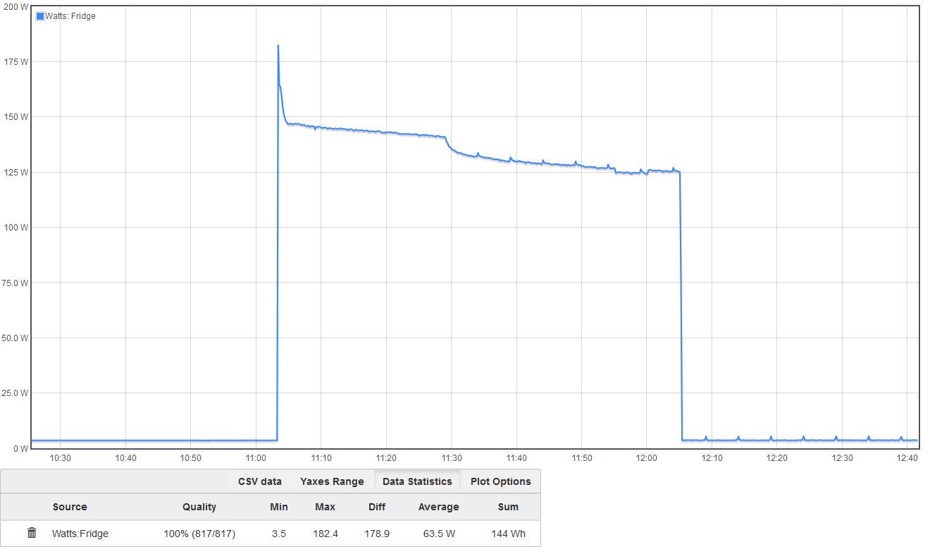
Maybe. Inrush can be brief, but most appliances draw a little more for more than a few seconds until they heat up to operating temperature or get up to speed or whatever. Like a refrigerator that has both a startup peak and decreasing draw as the cycle progresses. The time is hours:minutes
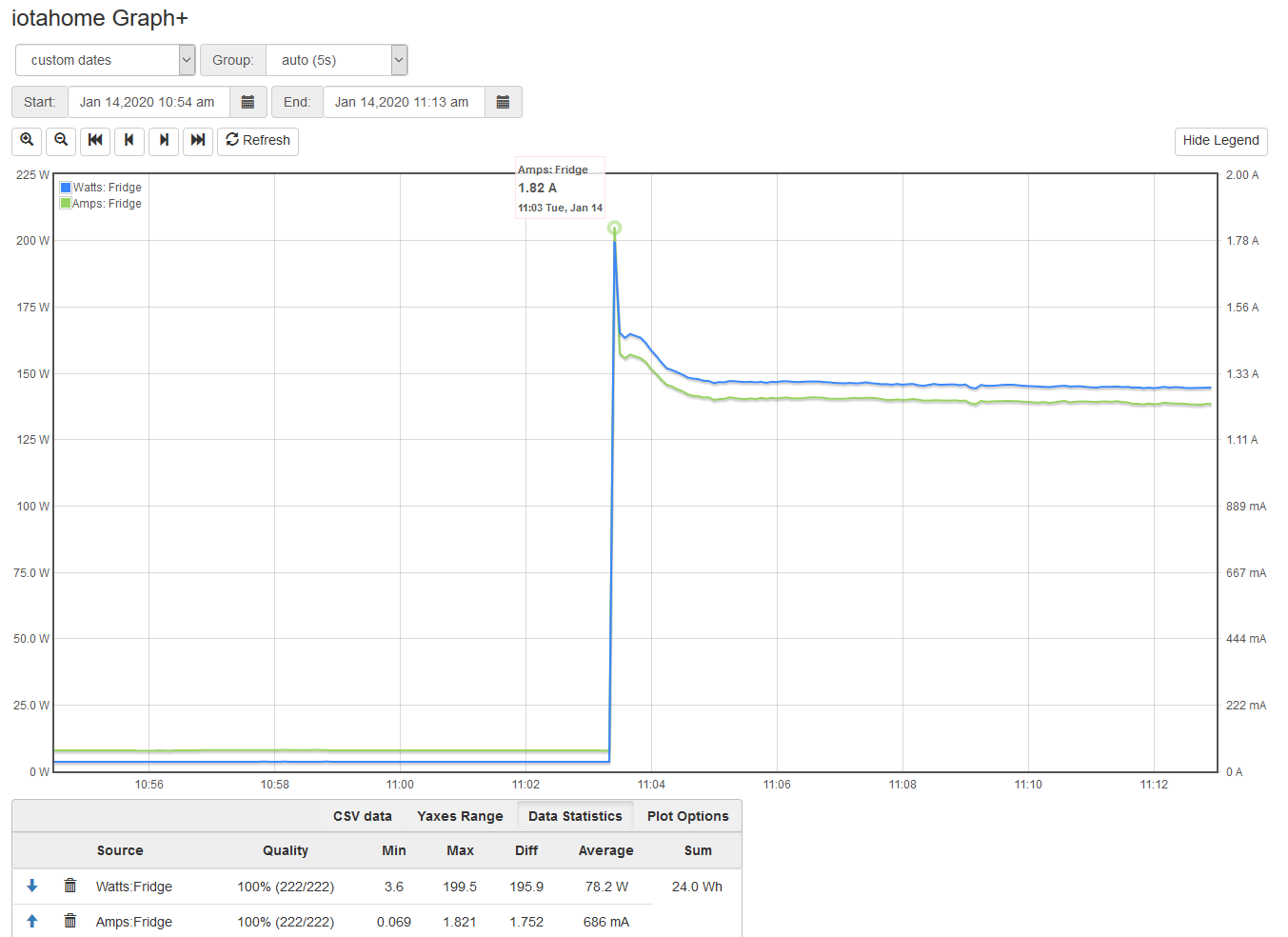
You can see in the max statistic at the bottom that the inrush peak is 182.4 watts. That’s the average over the grouping which is 10 seconds in this case. Zooming in to 5 seconds and adding the Amps you can see that the 5 second average peaks at 199.5 Watts and 1.82 Amps. Instantaneous Amps would be higher, but circuit breakers do not respond to instantaneous loads.