US dual-200A-panel dual-IoTaWatt install with power drain seek & destroy mission

I nearly bought a couple Sense units last weekend, and luckily IoTaWatt showed up a couple times in comments & reviews. :sweat_smile: Dodged that bullet! I’ve read the docs and a bunch of forum threads, but with the store offline I’ve been taking in the info slowly, patiently wishing I could undertake this project while stuck at home anyway. Now with the store back up, it’s time to stop dreaming and get started!

I’d like to eventually install solar panels, but figured I should get my current consumption under control first. We live in mid-Atlantic region with always hot summers but often chilly winters, too. Our least monthly consumption was last April at 2153 kWh, and most was July at 5750 kWh. Heat pump usage in summer will surely be the worst offender, but ~72 kWh on an exceptionally light day and almost 200 kWh on a mid-summer day is pretty nuts, and hopefully I’ll find some smoking guns that are addressable either with habit changes or equipment upgrades.

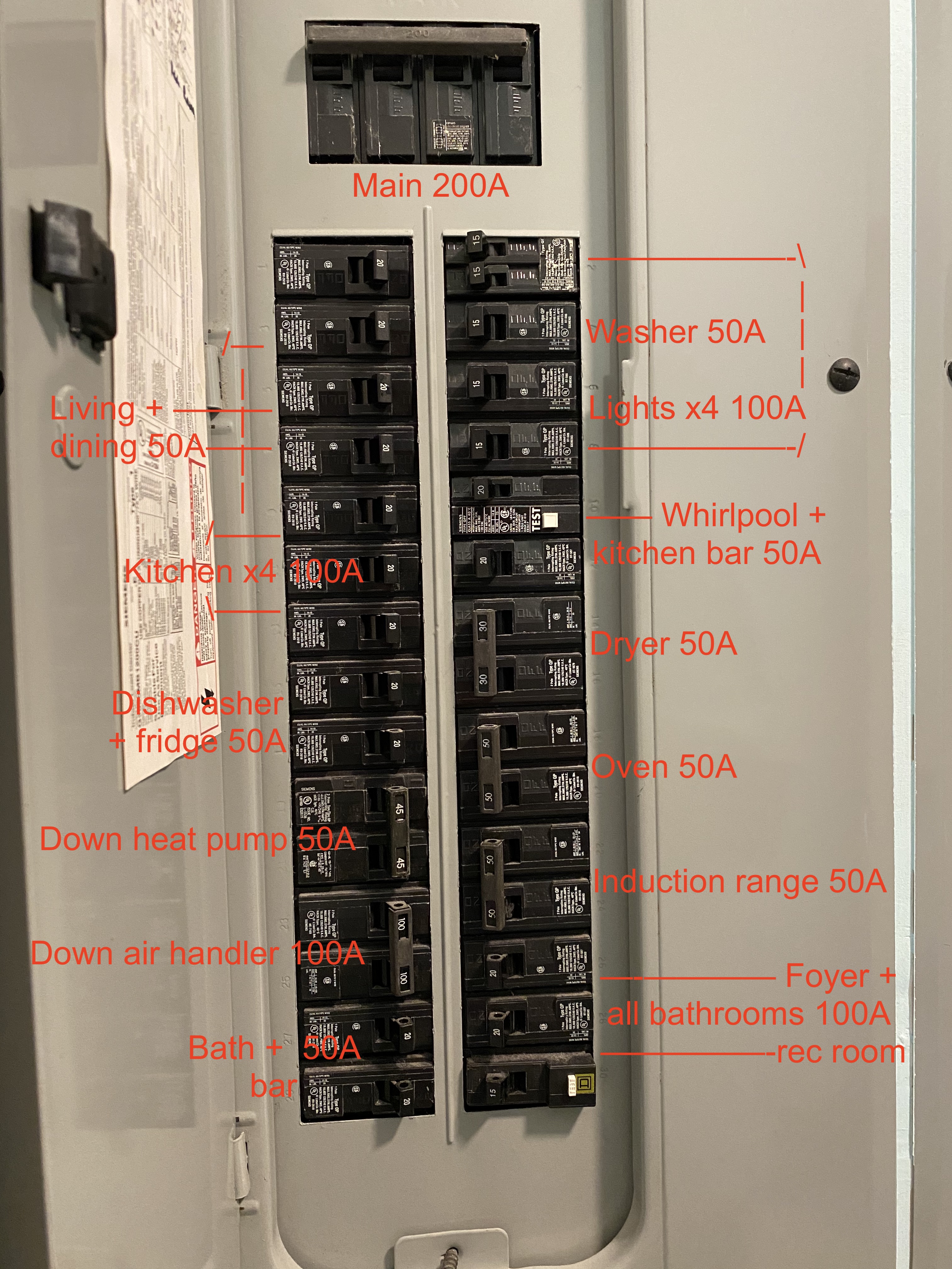
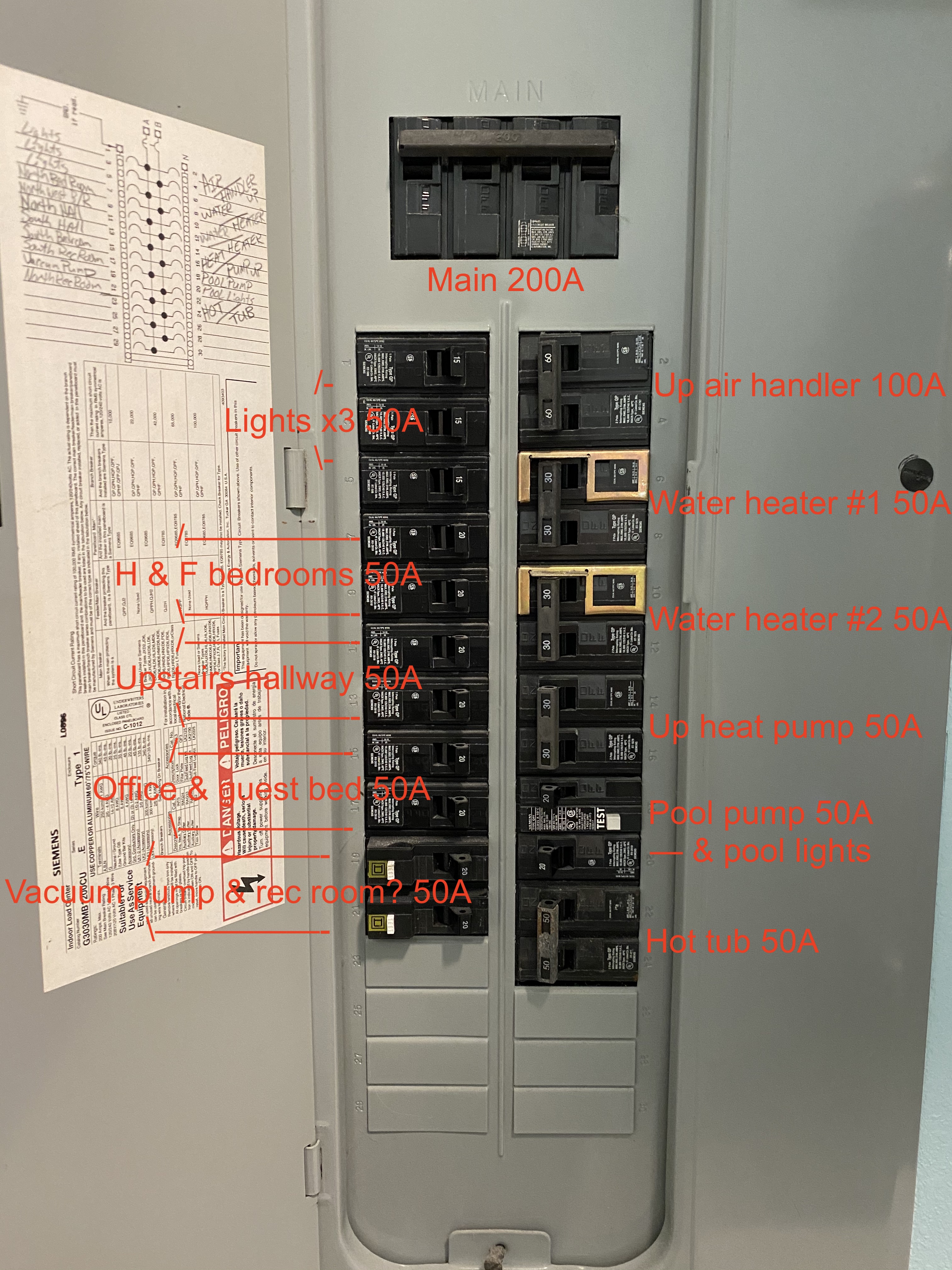
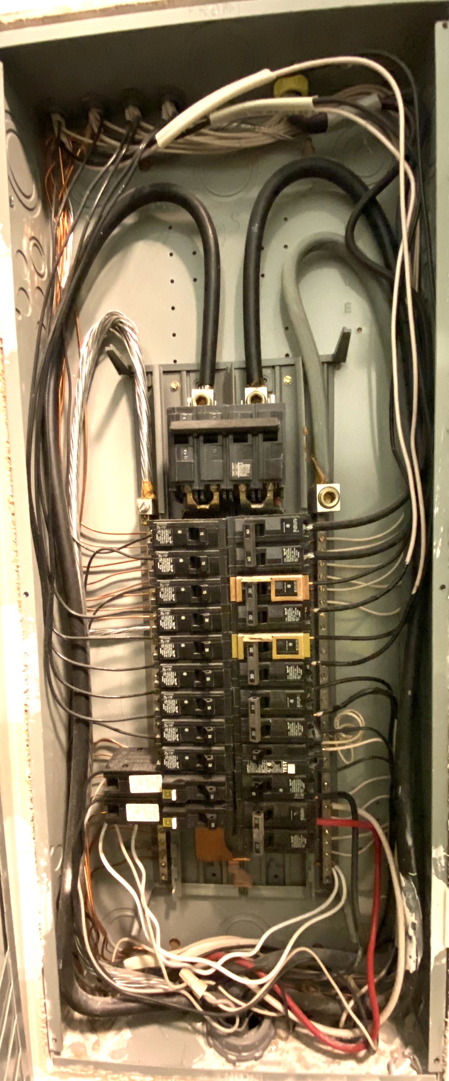
I have two main 200A split-phase panels in the laundry room. There’s also a main cut-off panel outdoors next to the meter, which is convenient. My plan is to start with 2 IoTaWatt units, 1 per indoor panel, and max them out in their CT inputs to get as full coverage as possible. The indoor panels are inconveniently flush-mounted into the wall, but if I can install a big double-dual-outlet Orbit-type box above the two panels, it should require the least drywall patching. Eye sores aren’t really an issue in there, anyway.

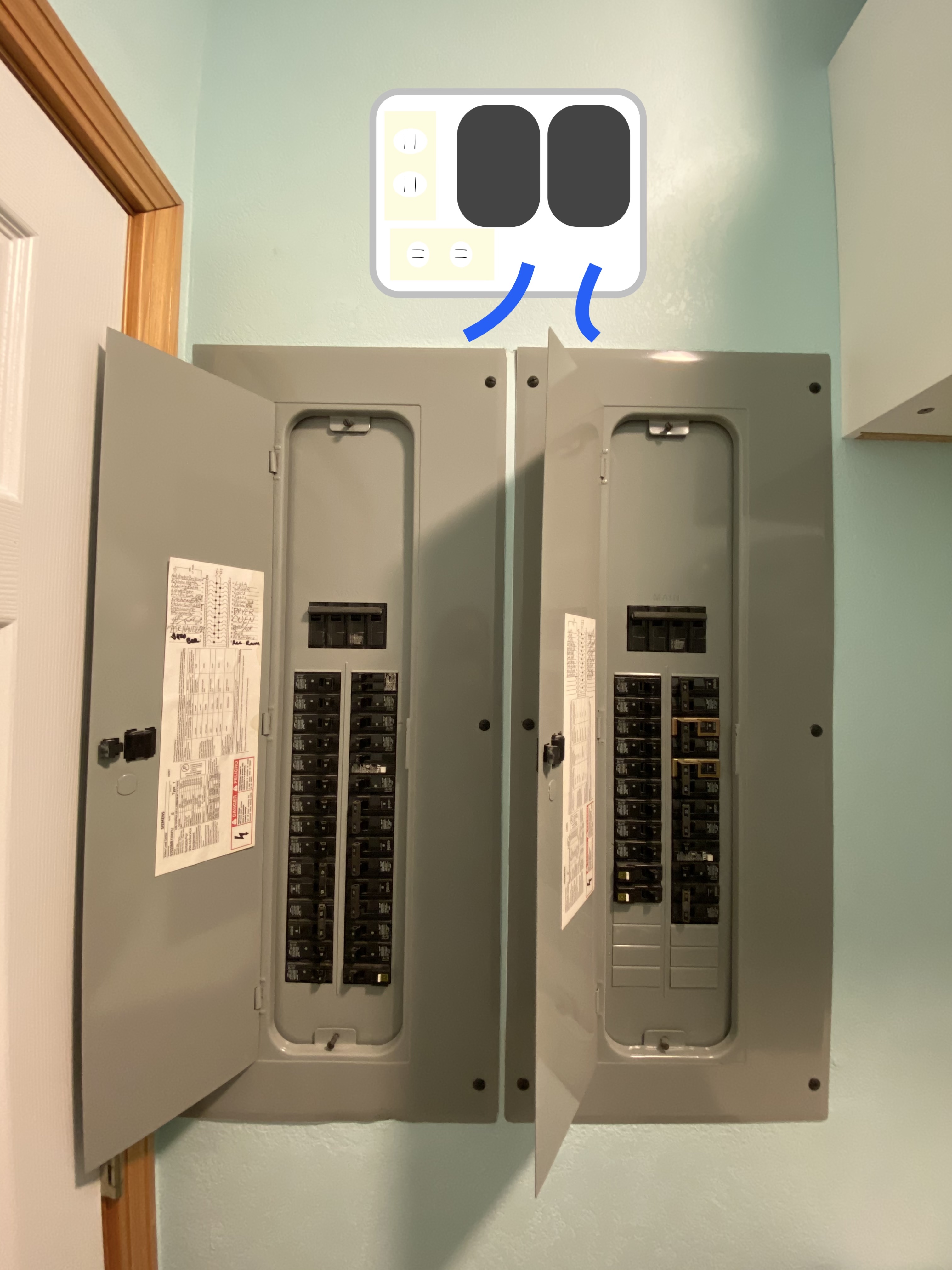
If I really want to try to capture as much detail as possible from the 2 indoor panels, I could put a 3rd IoTaWatt outdoors and measure the mains upstream instead of inside each indoor panel.

Next step: plan out which circuits to measure in each 200A panel and make a shopping cart of what to order. I’ll go back and reread some of the other case study threads, but first unknown to nail down is how many inputs I can expect to use.

My understanding is that there are 14 (not counting VT ref input 0), one of which I’d use for each panel’s main feed, leaving the other 13 which I could use for circuits or combinations of circuits coupled either with multiple conductors per CT or via 3.5mm stereo splitters. But in the store description of IoTaWatt, it says up to 12 branch circuits. Where am I losing that 13th? And if I move the mains measurement to outdoors, would that free me up to 14 circuit CTs on each indoor panel?

Thanks for tips, and looking forward to document my progress as I slowly set this up and eventually learn where all this power is going and if I can do anything about it before eventually sizing up a solar project! :crossed_fingers:

Hi Benj,

You will find that each panel has two mains cables, which uses two inputs. That leaves 12 for branch circuits. There is room for creativity here with splitters, but that is the basic math behind the general branch/mains statements.

I think most folks that have had an IoTaWatt installed for any length of time might confess that there is an 80/20 type rule when it comes to managing your consumption. I think that you will quickly find that there are a handful of big offenders that are actionable.

To that end, I would recommend that you make a list of the 240V appliances, their nameplate rating, and a guestimate of their duty cycles and calculate the estimated daily use. Plan to monitor the big offenders. Then look at groups of light/plug loads like a family room with electronics, lights and maybe a ceiling fan. Plan to try to do all of those with one CT. Individual problems are usually prominent in the graphs.

See if you could get a picture of all that with one IoTaWatt (4 mains and 10 branches). By subtracting the measured branches from the Mains total you can define an output that is the sum of the unmeasured loads. You can plot that. If there are some big spikes, you can try to determine what they are by the magnitude and timing.

Instrumenting everything is a big expensive job, and in the end you will see a lot of small numbers and a handful of big numbers. My recommendation is to start with the big picture and drill down rather than cast a big net.

I realize I’m trying to talk you out of buying an additional IoTaWatt. It could come to that, but I’d rather you find you really need it. I’m more interested in seeing you solve your problem as efficiently as possible.

Thanks for filling in that 2x mains gap in my understanding! One for each leg of the split-phase, makes sense. A follow-up on that: if I used 2x 400A CTs, so each would output 25mA at 200A, coupled with a stereo splitter, at least theoretically would that give me the same read on mains while leaving me with 13 inputs? (Not that I’ll need them all, but good to no my hard boundaries!)

Here’s the breakdown of CTs I diagrammed for myself yesterday before I posted, assuming just 12 branch circuit inputs available: 11 from one panel, 13 from the other.

Your advice to stick to one IoTaWatt is not falling on deaf ears, but I may as well get feedback on whether my initial plan was feasible to help me decide how to proceed.

A second IoTaWatt & CT set would not be a total waste, since once I get my own household under control, I’d want to reconfigure myself into a smaller future maintenance mode, and could gift the 2nd unit to a friend or family member to tackle their house. My dad is an electrical engineer who used to go around the house replacing light switches with timers (to his kids’ amusement and annoyance) and I think he’d get a kick out of monitoring his own consumption now.

1 Like

Some impressions from those photos:

Your mains are four 100A ganged instead of two 200A, so you may have four cables coming in. You might want to check to see if there are four and whether they can be easily consolidated into two CTs. Those types of mains can be L-R-L-R so adjoining breakers are different phase. I can probably tell if you post a picture with the cover off. About the 400A CTs - that would work.

My shortlist of suspects would be:

Hot Tub - Major offender. There are usually huge opportunities for saving there. Folks think it’s the heaters that use all the juice, but if you are circulating 24/7 the pump usually consumes way more tyhan the heaters. Reducing to circulate only a couple of times a day when heating works well. With respect to heat, evaporation is the whole ballgame. A well fitting floating bubble-wrap type cover will go a long way to reduce that.

Air Handler - At 100A, it sounds like you have electric strip heaters in there. That’s fine - if they rarely come on. I don’t see a furnace or boiler circuit, so if you are using just heatpumps, another form of supplemental heat may be in your future for cold mornings. BTW, the rule of thumb is to NOT setback heatpumps at night when you have electric strip heaters. Recovery in the early morning is a real uphill climb for them.

Pool Pump - again, pumps are not real high wattage, but their duty cycle makes up for it.

Heat Pumps - What can I say, old ones bad, newer inverter good.

Water Heaters - A typical tank is about 2kWh/day standby loss, then it’s all about usage - unless you have a recirculator system, which while convenient is very costly. There are on demand pump systems that can mitigate that.

Those are the biggies. Secondary is:

Dryer - it is what it is.

Oven and range - while they can draw a lot, they are relatively low use appliances in most households and don’t usually contribute much to the total.

For each panel, if you measure the above, you can then compute the sum of the remaining. If there is a steady baseline of usage there, you can have your father put in some timers. Otherwise, you may be able to pick out any unmeasured problems just looking at the graphs.

1 Like

I recently did a two Iotawatt install though on one panel (it’s here).

A couple of random thoughts…

First, you are doing really well to plan ahead. The physical install simultaneously easy (in that it is simple) and really hard in that it is always going to be space constrained and difficult to make look pretty.

You have a fundamental decision to make – are you curious and want to measure things that really are not actionable (but are interesting), or do you want to limit your scope (and so effort) to just actionable items.

Range and stove type appliances are good examples: It’s interesting to know exactly how much you spend cooking a meatloaf, but it is not exactly information that will change your behavior. With LED lights the same is true of most room branch circuits (now maybe different if you have a lot of incandescent, or exterior lights). Even a fridge(s), unless its pretty old and you are looking for an excuse to change, it’s unlikely that info will change your behavior.

I opted for interesting – I put in two on one panel, and even then I often wonder about circuits unmonitored even though they are pennies a month.

Decide. The CT’s and units are not that expensive, but the physical emplacement gets harder the more dense you want. Better to do it once than come back.

Next: I would open up that sheet rock (carefully) and see where all the wires go. My GUESS is you will not have room to put it where you show, as there’s likely 40 or so wires bunched up in there going upward, too short to move aside. You may find it easier to go to one side or below (unless by chance a lot of the wires go down?). Sheetrock is pretty easy to fix, before you decide on a box(s) look.

I’d also suggest you MIGHT want to go to two different places for two IoTawatt’s, just to reduce the number of wires that need to come out and go to one place.

Finally if it were me I might not actually put a box in, but a cover. You might just mount some wood in the wall behind the sheetrock to mount the panel through, and not try dealing with conduit. I am not an electrician, but not sure you need conduit if it’s going to end up behind sheet rock anyway, and it might make your runs a lot easier (if less pretty until you put the cover on, thinking like the covers often installed beside whirlpools and such, just a plastic door that pops off but looks finished.

2 Likes

Thanks for your ideas! Here’s an under the covers look:

Looks straightforward and lots of room.

Confirms that mains can be 2x200 each or 2x400 combined with splitter. It also looks possible to bend the mains so they cross in opposite directions, which would allow using one 36mmx400A CT. Would recommend the power be off if there is an upstream disconnect and that an electrician do this.

From what I can see:

The two heat pumps are 2-wire, so one 50A CT each.
The two air handlers appear to be two wire, so one 100A each.
The oven looks to be 3-wire, but swapping it’s CB with the dryer above would appear to give some slack to use one CT with both conductors, one reversed. 100A for oven, 50A dryer
Induction range probably 3-wire 2x50A