Awesome project! I’m super glad I saw that review on Amazon for Sense pointing out this. I’m doing my research on my setup first before ordering but I’ve ran into a snag. My outside panel (attached to meter) doesn’t have wires running to it! Looks like the mains are provided by 2 metal bars covered in heat shrink tubing or something similar. Pics attached showing what I mean. Unless I’m mistaken my mains are the 2 black covered metal bars coming up at the bottom. I was able to easily identify the cables/breakers other than that.
Is there a CT that would work in this kind of situation…?
There are CTs made for bussbars, but they are special order and I’m not sure you have enough clearance to get them in anyway. So lets explore some other options:
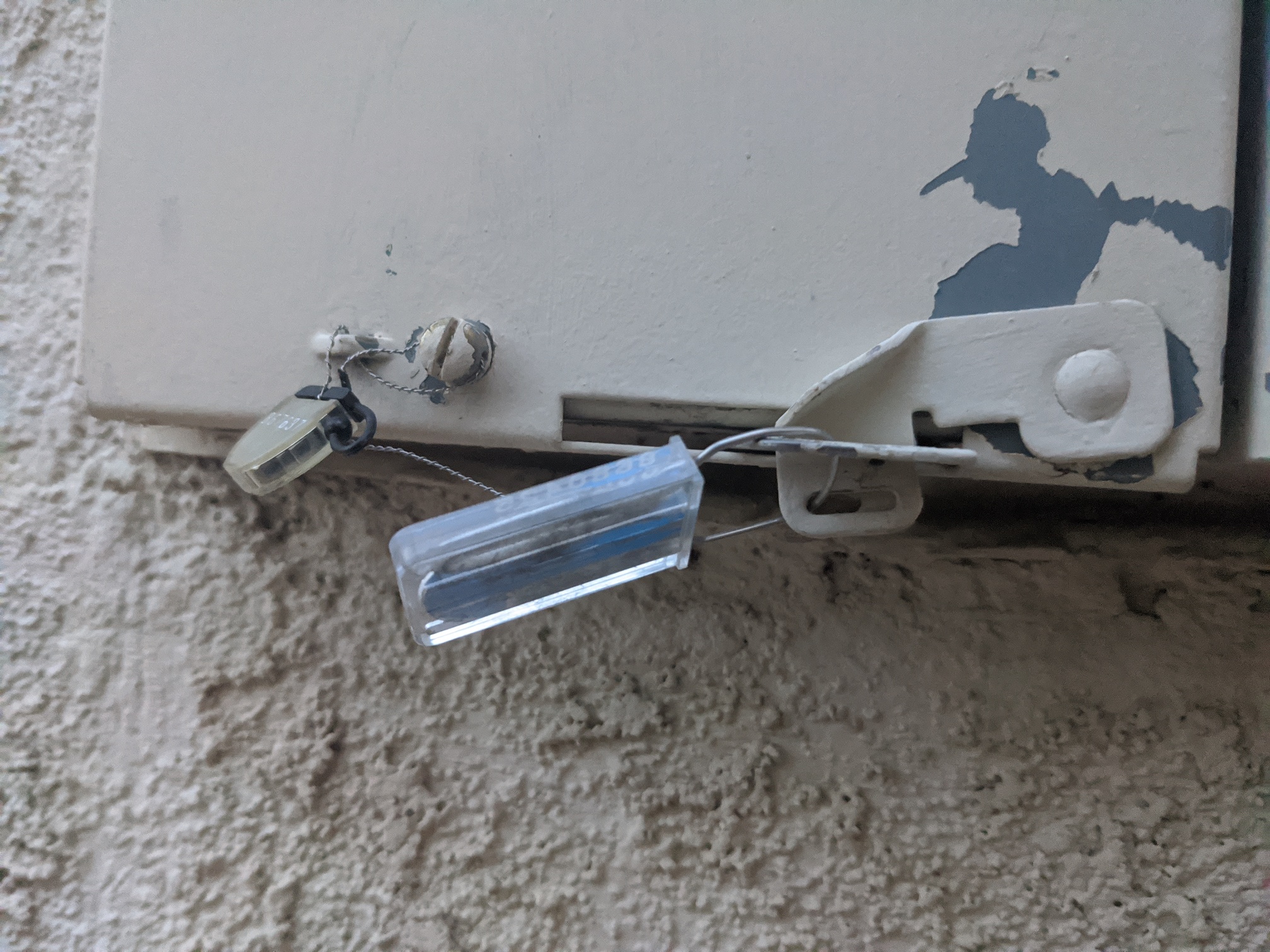
What’s under the cover to the left of the meter? I’m curious if the there are mains cables in there feeding the meter. If so, that would fine. It doesn’t appear that cover is sealed.
If that’s a dry hole, then where does the service come in? I don’t see a main shutoff in that panel, and there must be one somewhere before the meter. What’s that box on the right?
I have clamp type CTs that are 1" opening. what is the width of the bussbars? (carefull!)
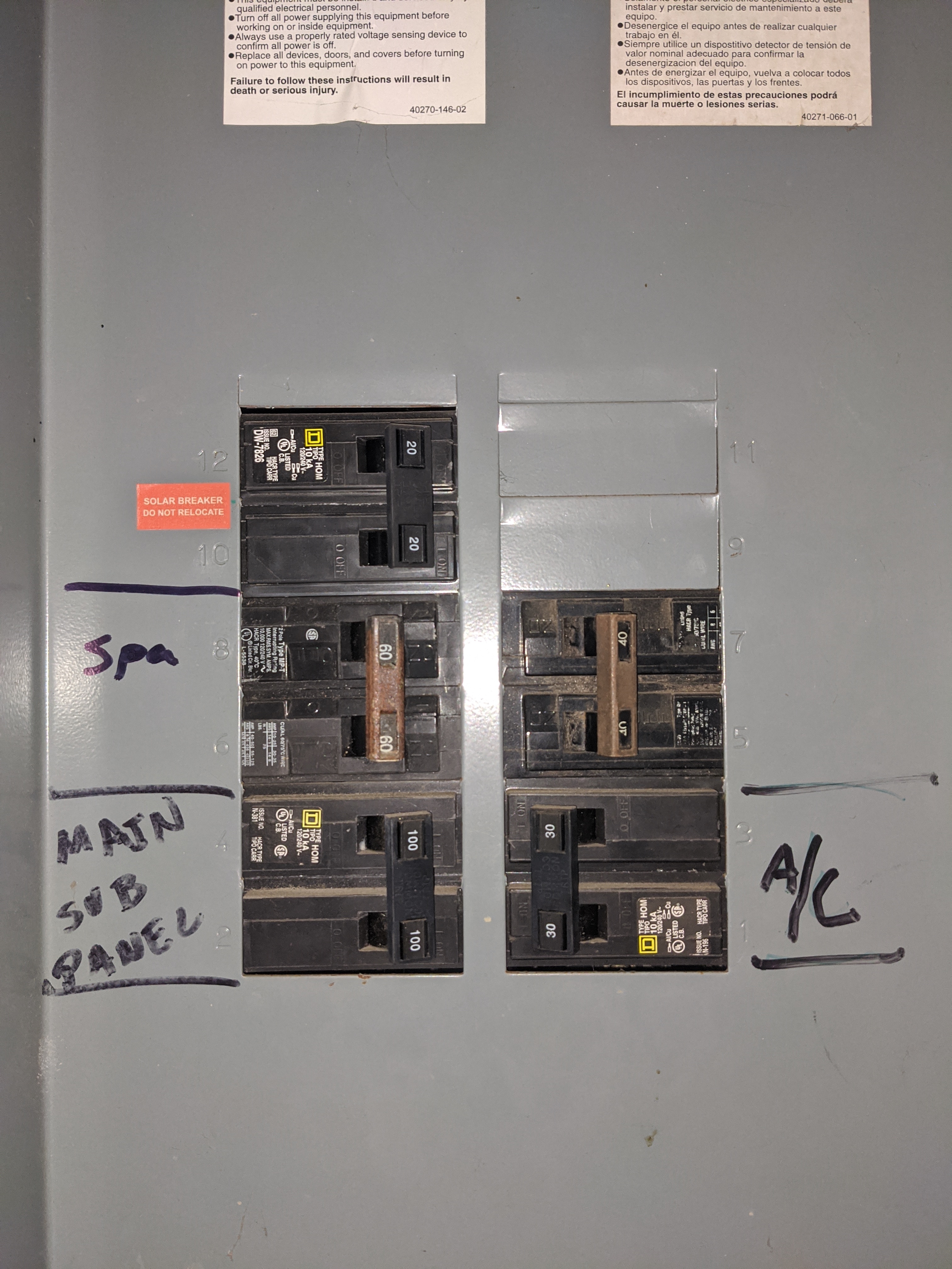
If all else fails, you can put CTs on the four breakers. It looks like you could bundle the three wires of each phase on the left and put a 200A CT around each bundle (black/red). On the right, the top breaker looks unused, and the wires on the other seem to run up and exit the top left of the panel with a lot of slack. Maybe you could run them into the 200A CT as well, or just put a couple of 50A CTs.
I’m guessing the 100A goes to a branch panel in the house, the 20A and 30A are appliances or a well pump, and the 60A maybe another utility branch panel?
Thanks for the super fast reply! Now I learned a new term, bussbar.
The bussbars are 1" wide, about 1/4" thick. There is about 1/2" of clearance between the bar and the black plastic back of the panel. The 1/2" clearance lasts for about 1" going up the bar before it bends toward the back wall.
The panel to the left of the meter has tamper seals on it. PG&E probably doesn’t want me opening it. I assume the main shutoff is in there.
The panel on the right is my PV disconnect for my solar panels.
As for the breakers, left side top to bottom:
20amp/20amp - Solar feed from panels/inverters (no battery, net energy metering)
60amp/60amp - Hot tub sub panel
100amp/100amp - Main house sub panel (garage)
Right side top to bottom:
40amp/40amp - Unused
30amp/30amp - A/C
At least that’s what it looks like based on the labels and my testing.
Ok, based on that, it looks as if you could group two bundles of cables from the main panel, hot-tub, and AC through 200A CTs and call that your mains. One 50A on either of the solar wires will cover that.
The wires from the AC have a lot of slack, so you could easily run each phase with their counterparts from the other side as they run across the top of the box, or you can run the alternate phases backwards. It all comes out in the wash when you add the mains together.
My primary goal here is to monitor the power usage of the breakers in this panel anyway. (hot tub, ac and main sub panel, plus the solar)
So would I put a 200a CT on a combination of the breakers (one for each leg), and then put in addition to that put another CT on each separately? In that case I need the following CTs:
200a + 200a - all (except solar)
50a - solar
100a - main sub panel
100a - hot tub sub panel
50a - A/C
Great! Sounds like I have a plan then when you start shipping again.
Out of curiosity since the A/C has two 30a beakers, why does a 50a CT cover it? (I previously didn’t realize that I would of course need both legs of these 220v breakers). Same question applies for the 60a hot tub.
Also, does the software running on the main iotawatt unit have the ability to combine the data to create the net import/export directly (and shown in the web interface/JSON) or do I have to do that math on a separate database server?
The CT can handle it’s full rated capacity (and then some). The electric code requires that the circuit-breakers used to protect an appliance be able to handle 25% greater load (maximum load 80% of rating). So that says the AC, with 30A breakers, should not be greater than 24A per breaker, or 48A total. My recommendation for one CT is based on passing both conductors through the CT in opposite directions. There seems to be plenty of slack to do that. If the AC doesn’t have a neutral wire, then you will be able to just monitor one conductor and double it. Either way, the 50A CT is fine.
Same math on the load, 80% of 60A is 48A, but here I have specified two 50A, one for each conductor. If you are inclined to remove the cable ties to make enough slack to pass both conductors through on CT, you can use one 100A CT.
You can get net usage, but not import/export. With Graph+ on the IoTaWatt, you can produce the daily import and export, but longer term totals will require using an external database the can integrate the detailed data. PVoutput is free, does a good job, and has a mobile app as well.
The IoTaWatt can produce net usage from all these inputs, so if you are billed with net-metering, it should be fine. If you have separate rates for import vs. export, you will probably need a database or PVoutput.
The data for import/export is there in the IoTaWatt, the issue is the processing needed to extract it would compromise sampling. I’m looking at ways to do it in the background.
Understood on the CTs, I trusted your word on it, was just curious how it worked for my own knowledge. Also yes I read your documentation already and am aware of the need to pass the wires through opposite directions.
At the end of the day I really just want to know what my “luxury” items (A/C, hot tub) are costing me versus my normal electrical stuff (main sub panel). I already get historical usage data from my electric company PG&E, but not real time/last 24 hours. I’m planning to use this to supplement. (I also use Home Assistant, which I plan to integrate with using JSON, so I can get alerts when power usage exceeds certain thresholds. Like a warning to stop using the A/C so much!)
Based on what I’ve read on your documentation, and what you’ve said above sounds like I’m heading in the right direction.
If (in the unlikely event PG&E accepts my request to open the tamper sealed panel with the mains) I could somehow get 200a CTs on the mains, is there any benefit in this situation? Or since I’m already putting CTs on everything else would it just be redundant?
On an unrelated note, I’m lucky enough to be able to mount the main iotawatt unit in my garage (there is already an unused conduit from the outside panel left over from an old project). The regular 110v outlets there come off of the main sub panel. Is it okay to connect the Voltage Reference transformer to one of those outlets? Or do I need to pull a circuit off of the outside panel directly?
Lastly, what’s the maximum length the CTs cable can be? The main sub panel is about 50’ from where the iotawatt can be mounted. Could I use 3.5mm extension cables to route additional CTs to the main sub panel (and so avoid having to buy and mount a second iotawatt main unit over there). Not sure if resistance from the extra length would too severely impact accuracy/functionality.
Again thank you so much for your prompt replies, and stay safe!
It would be redundant. The only possible benefit might be a little better accuracy, but I don’t believe significant enough for the trouble and expense.
You say the main sub-panel is 50’ away and so this would be presumably be 50’ from there. So 100’ from the meter panel. I think it would be OK provided there isn’t any appreciable load on the circuit the outlet is on. A 15A breaker in the meter panel would be ideal.
50’ is a long way. Resistance isn’t really a big factor with the hefty CTs in the shop, but noise can be a problem. Most folks doing what you are suggesting use CAT cable and wire 4 CTs through a single cable. They are twisted pair and good quality for a signal.
Okay sounds good. I have plenty of Cat5 and Cat6 cable, and that would be an ideal setup for me. Would I cut the CT wires and solder it onto the Cat5 (one pair per CT)? Or is there a better way to make the connection?
I’m super excited to start on this. Guess I’ll work on running cables and conduit while I wait for your shop to reopen. Thanks!
I realize this is an older thread, but I wanted to comment just in case anyone else runs into the same thing.
Most likely there is not a main breaker under the utility seal. Instead, all of the breakers are considered main. This panel is what’s known as a “rule of six” panel. The name comes from the NEC rule that allows you to actually have not just one, but six main shutoffs on a building, provided they’re all grouped together. Sometimes this is seen as a split-bus panel, where there’s a main section with six breakers, and another section that’s actually a subfeed from one of those breakers, and contains more breakers itself.
The reason this was done back in the day is that large double-pole breakers (>60A) were very expensive, and so to save costs, all the major 240V loads were powered from the main breaker section, and all smaller loads from the subpanel (either in the same enclosure, or elsewhere). That way you could have 200A service without needing a large expensive 200A breaker.
This is no longer permitted in modern code, because it does create a safety issue – it’s not possible to deenergize the buses on rule-of-six panels yourself to work on it. The only way to deenergize that panel for maintenance is to call the utility and have them pull the meter. Panels that were installed under the old code are grandfathered under the newer codes, so it’s still legal to use, and there are a lot of them out there. Be extremely cautious working inside it.
Thank you very much for explaining this, as my house has an outdoor panel with 6 x 240VAC breakers, and one of them feeds a subpanel in the garage that has all of the 120VAC breakers in it.
Now I understand why it is designed this way much better.
Again, thank you for taking the time to share this history!