My new IotaWatt has arrived and I have started the configuration. I am hoping to use the Emporia 50a and 200a CTs that I have but can’t find much on the specs. There is no brand on them but the 50a ones have 50a0922 printed on them. Emporia specs show they are both .333 volts. Looking at the Emporia manual section 6.4.2 I am thinking this means I should choose Type VT, Generic, with Cal = 150 for the 50a and 600 for the 200a. Phase lead 2.0.
I see some earlier posts on here about Emporia but not answered for these devices.
Am I on the right track here? I am waiting on adapters to convert the 2.5mm jacks for the IotaWatt 3.5mm sockets, so can’t test just yet.
Have not tested the Emporia CTs, but have successfully used their Rogowski coils which are indeed .333mv output, which only uses 33% of the IoTaWatt ADC range, but nevertheless has given good results with the Rogowski on mains.
You have most of the adaptation correct, except:
- You would still use type = CT.
- You must remove the burden resistors inside the IoTaWatt for those channels using the Emporia and set the burden value to 0 (indicates no burden) in setup for those channels.
- Your Cal calculation is correct.
- I have no idea what the phase lead is, so 2 is as good a guess as any.
Please post back with your results.
Thanks Overeasy, but …
If I choose type = CT there is no field to enter the Cal for the 333mv input. It wants Number of turns. Do I need to calculate this? Looking in the config.txt file I can see the number of turns is listed for CT entries but not for VT.
Also the manual does not give any explanation for what Phase means in this context. With suggested values of 0.2 or 2.0 I can’t see how it would be related to 3 phase power.
For the record I am in Australia, with 3 phase power (“wye” 4 wire) with no solar. I intend to get the system working as if I only had single phase (i.e. no inputs from anything on Phases B and C). Once working, then plug in the CTs on the other phases and implement as “Derived Reference” as per the manual. It is just residential and I doubt any phase would ever reach 50 amps (on the mains), let alone the individual circuits.
Turns are irrelevant with voltage type CTs.
CTs (and VTs) are transformers and the output signal is phase shifted from the input signal. The difference in phase shift between the two must be corrected numerically to obtain the most accurate results. The supported CTs in the tables have measured phase-shift attributes. Again, 2 is probably as good a guess as any and won’t make a whole lot of difference for anything with a power factor of about .80 or better.
Thanks. I get it now. Once the burden value is set to 0, the input screen changes, and then asks for Calibration value instead of turns. I have made those changes.
Still awaiting the 2.5mm to 3.5mm adapters I ordered elsewhere, so frustratingly have not been able to test it. Hopefully before I go away for a couple of weeks.
Emporia’s Rogowski coils have 3.5mm jacks and plug in where the 200A mains go. Are you sure your 200A have 2.5mm jacks?
The 3 x 200A CTs (for the mains) are 3.5mm. The 50A ones for the individual circuits are 2.5mm. I was surprised that the device has the different sized sockets, preventing them from being interchanged.
The 2.5mm to 3.5mm adapters arrived and I now have all the inputs and phases configured and working. I am yet to check on accuracy.
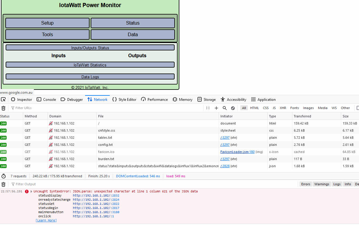
The graphs work for each input and output, however each of the sections under Status is entirely blank. A corrupted file?
For anyone else planning to use Emporia CTs, the jacks (mainly 2.5mm ones appear to be slightly thinner than another 2.5mm jack I have. So they feel like they could easily come out of the adapter sockets. Next task will be to get some 3.5mm jacks and rewire the CTs. I did not want to do that until confirming they worked.
screenshot? Also, please turn on the Javascript debugger (PF12) and select “network”, then refresh the status app, take the screenshot.
I tried rebooting then powering off and on. Tried a few times with all producing the JSON parse error. But the column numbers were not consistent. I could not see which file was the problem.
When first set up, my Inputs were listed under Status. Also showed Statistics (and I think there were links under the Data Logs. Then I realised I had the A B C phases incorrectly attributed for a couple of inputs. So I changed those and rebooted. Then noticed that nothing was showing under Status.
I can’t tell what file has the Json parse problem, but its most probably the config.txt or tables.txt. Try downloading config.txt or otherwise accessing it (remove SDcard). Feed it into Json lint and see if its valid json.
Thanks, solved. Examination of the config.txt showed one of the inputs had a “loops” key in addition to “Cal”. Editing the entry did not solve it but deleting and reinstating it did.
Update: A few hours later I noticed everything under Status was blank again. I had not done any changes in the meantime. Reboot, still no display. I searched config.txt and it looked fine. Both the files you suggested tested as valid Json.
So I deleted one of the inputs and the Status immediately showed. I then reinstated it and rebooted and at present it still displays as it should.
However I suspect it is under-reading substantially. I will check things in the morning (late here now) and raise as a separate topic if not solved.
I am getting some odd readings …including flpping between positive and negative. Before seeking any further answers I am going to check everything and compare to my clamp meter. Maybe start again from scratch in case there is some cache affecting things. But that will have to wait a week or two as I will be away.
After parking this for a while I am now getting more consistent results. I think the flakey results was due to a poor USB power supply. But the Cal figure I need is not 150 for the 50A CT. Specs show .333v which earlier you agreed 150 was the correct calculation. But the reported readings are wrong. I think it should be 300 as my testing shows this is reasonably close to the watts on the appliance I was running. For the 200A CTs, about 750 seems pretty accurate.
I still need to refine those figures with more testing of high and low amperage devices. Should I fiddle with the Phase lead setting of 2? Any tips on getting accuracy? What accuracy should I expect … about 2%?
Hi Steve
What 5V USB power supply did you end up getting to help improve the results you were getting?
While mine is working fine on a 2.0 amp unbranded charger I intend to get a better one. Not sure where I got it from.
The recommendation is to use a Raspberry Pi charger. I have one but it is hard wired USB-C while the IoTaWatt is micro USB. Maybe there are micro USB versions or removable cables, but I have not seen them.
You reminded me to get moving and find a decent one.
There are heaps of the micro usb ones on ebay.com.au (search for “raspberry pi 3 power supply” (the RPI 4 ones are the USB-C ones).
Having said that, they are all pretty showing as 2.5A. I wonder if that is ok? Hmmm
im in the exact position as @dabbler68 , ie im trying to use 3x Emporia 50a CTs (along with 4x “normal” AcuCT-H040-50 and 2x AcuCT-H100-200).
I also ran into the blank status / json error in Firefox dev tools, at the exact same step as dabbler, however i only had to delete the 2x Emporia inputs i had added, and reboot the iotawatt (all via the web GUI, and no need to access json config directly) , and all was back to normal.
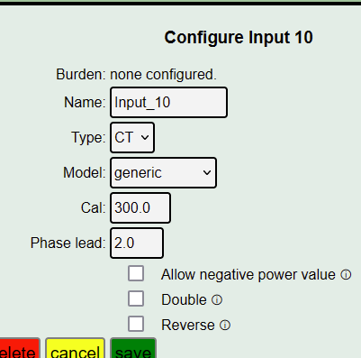
I then tried using model = generic, and dabblers Cal= 300 and Phase lead = 2.0 , and i seem to be getting very accurate readings (to be clear, on a Emporia 50a input).
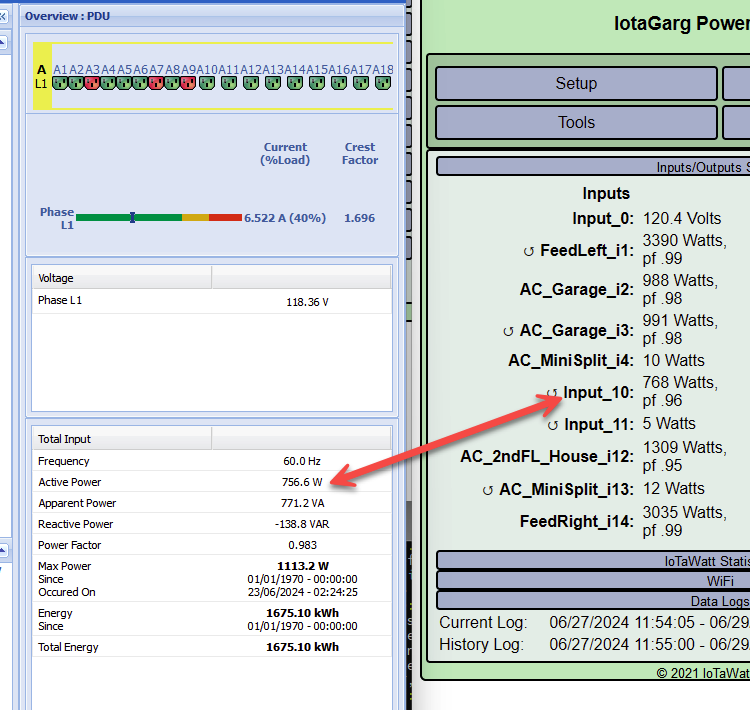
Im lucky in that this is a dedicated electrical circuit, that goes to my rack, where i have a Eaton ePDU (only device on circuit), so i can see the load on that. and it seems to match up (see photo).
Will trace out the electrical circuit to be 100% sure the breaker label is correct. I can also re-confirm all this as i have a 2nd dedicated circuit also going solely to a 2nd Eaton ePDU that i will see if results are same.
so will update this post once i finish / confirm that reading from the 2nd emporia CT with these settings.
I feel pretty sure my erratic reporting etc was due to the power supply. I took the advice and bought a couple of the correct Raspberry Pi chargers (one spare) and no more such errors.
As for the correct settings for the Emporia 50 amp CTs I now have mine set to 150 turns and 2.0 phase lead. I think my 300 turns setting may have been when I had not physically removed the resistors inside the IotaWatt.
For anyone considering these the 50 amp CTs supposedly have 2.5mm jacks but they are actually smaller than that. So using 3.5 to 2.5 adapters they are a loose fit. I recommend getting the correct 3.5 plugs and soldering them on. Similarly the 3.5mm plugs on the 200 amp CTs are smaller than standard, and are a loose fit in the IotaWatt. I am not using them.