Hi, I received some version 5 boards but in old version 4 cases. They have the two additional VT circuits which are populated with resistors but not connectors.
Is it as simple as putting connectors into place and making some holes in the case to use them for additional VTs or do I need to also update firmware?
Many thanks - the IotaWatt is a brilliant project!
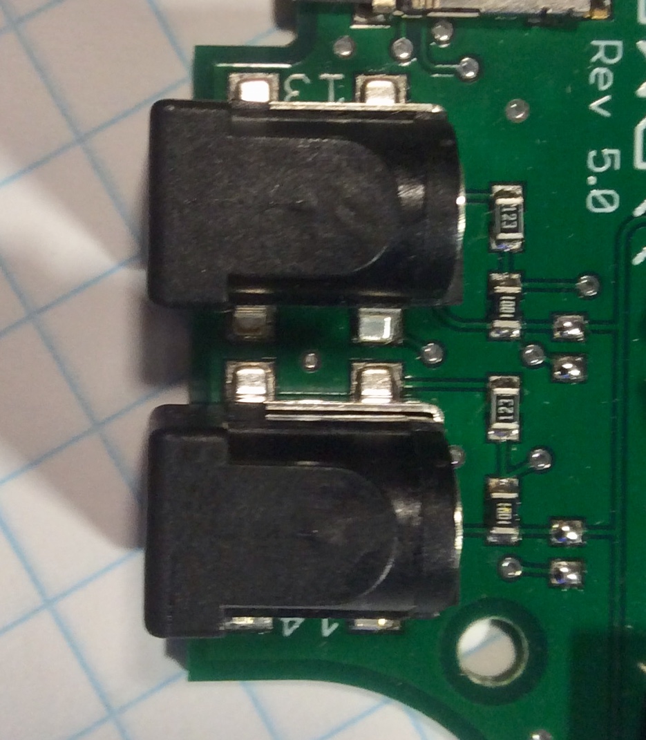
You’re right. The last 100 or so V4 actually have V5 PCBs without the additional VTplugs. It’s a little more complicated than just adding the plugs. You would need to remove the two shunt zero Ohm resistors nearby, and add 12K and 1K resistors in the vacant pads as in this photo of an actual V5 board.
My mistake. I guess the 12K and 1K are already there. (1001 and 102 are the same). But there should also be two zero Ohm shunt resisters that need to be removed.
No, the burden value only applies to when the channel is used for a CT and should be left as is.
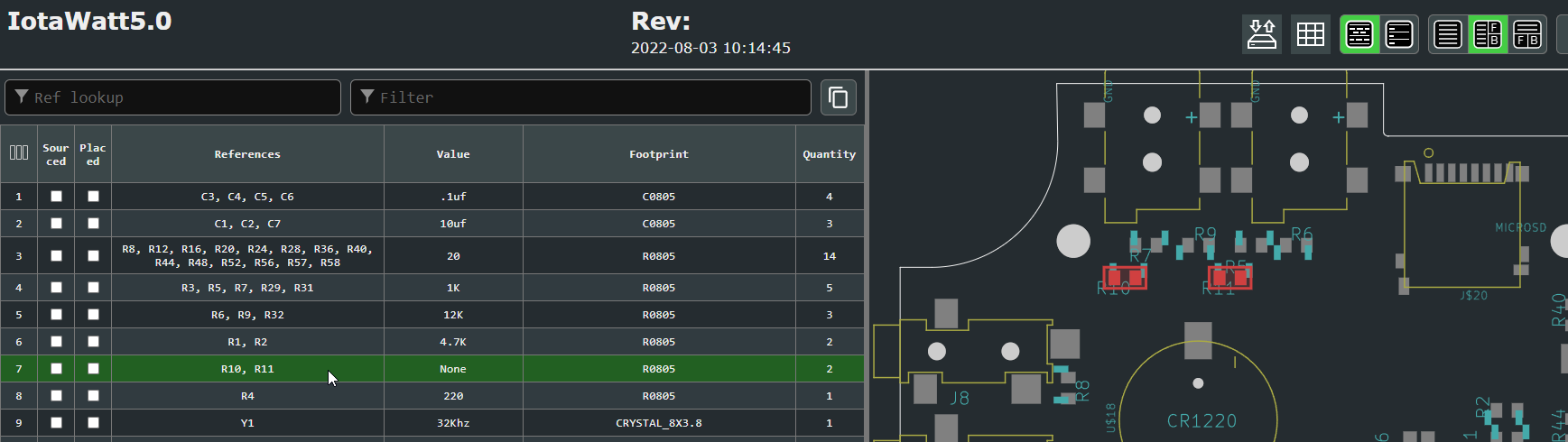
I apologize for bringing up an old topic, but it’s right up my alley for my question. I am looking at building an iotawatt v5. I brought the .brd file into kikad and built an iBOM. While looking at it, I saw the listing for 2 zero ohm resistors:
I was curious what they were for, so I did a quick search and found this thread. So now, if I read correctly, you’re saying that the zero ohm resistors are NOT needed in the v5 design, and that I should just leave the pads unpopulated, but the 12k and 1k pads need to be populated? I just want to make sure I have that right so I don’t blow things up. Thanks.
Right, if you populate the two barrel-jack 12K and 1K resistor, you should omit the zero-ohm resistor. Basically, those resistors replace the insertion switches (NC) of the barrel-jacks, simulating the presence of the jack with nothing plugged in. So, the choices are:
Populate the barrel-jack, 12K resistor and 1K resistor.
 Thanks.