Hi,
I have to following setup:
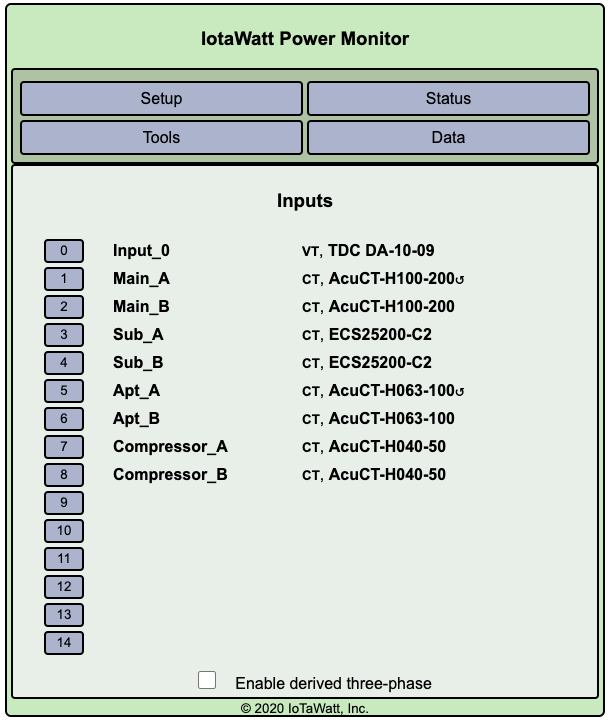
200A main panel called Main (Has CTs on the input side called Main_A, Main_B)
100A sub panel feeding off of the Main panel called Apt (CTs called Apt_A, Apt_B that are after the 100A breaker in the main panel)
The main CTs should always read a higher wattage as it is all the breakers (including the Apt sub panel.)
Challenge is that Apt_A+Apt_B reads higher than Main_A+Main_B which shouldn’t be the case.
What am I missing?
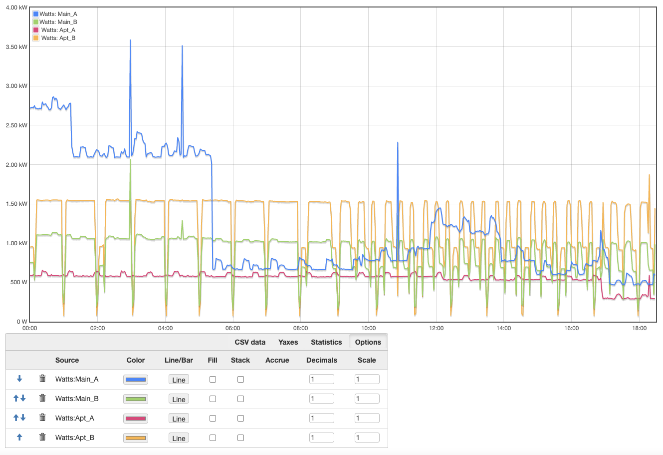
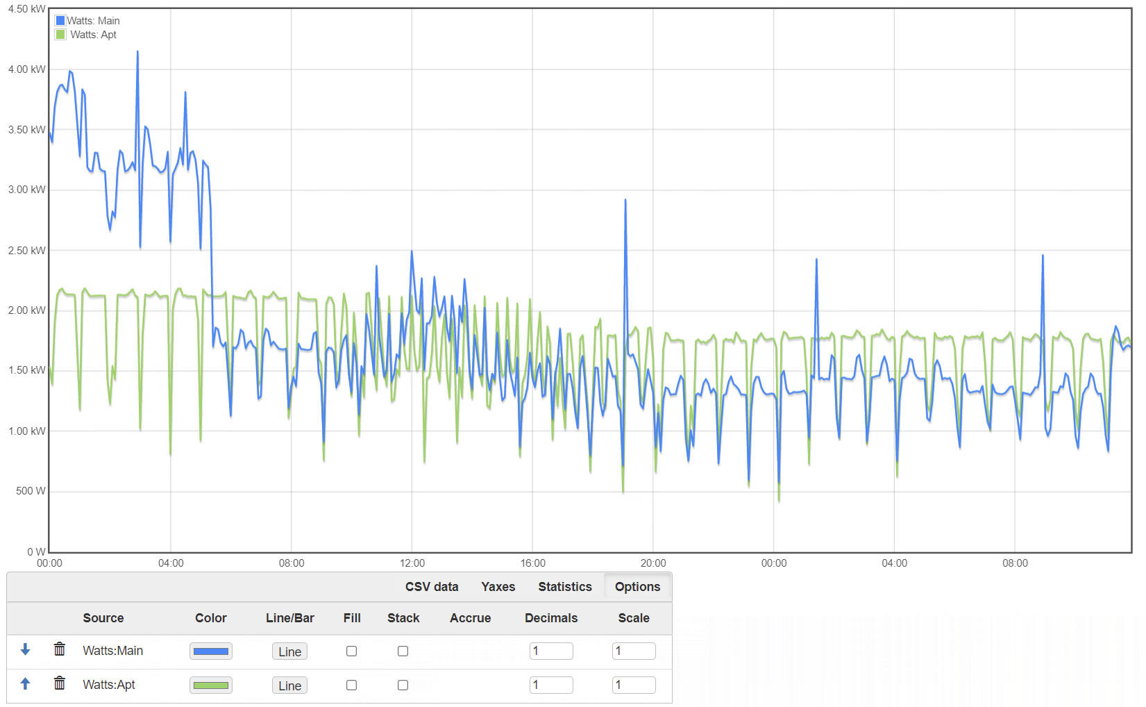
Picture of the combined Main_A+Main_B (Main) and Apt_A+Apt_B (Apt) showing the difference. Green should never be higher than blue, hence my confusion.
Thanks!
I think it may be a configuration problem. If your order was 122923, I see:
2xECS25-200
3xAccuCT-H100-200
2xAccuCT-H064-100
Your configuration has 4xAccuCT-H100-200 and 2xECS25-200.
Are you sure two of those CTs are not AccuCT-H064-100?
Sorry, had the incorrect screenshot (great catch) - I had tried changing the config fir Apt from AccuCT-H064-100 to AccuCT-H100-200 to see if it made any range differrence.
They are as follows:
Mains are: AccuCT-H100-200
Apt are: AccuCT-H064-100
I fixed the input screenshot in the first post.
Thanks!
Any other thoughts? Can’t rely on it until I figure this out…
Again, CTs are as follows:
Mains are: AccuCT-H100-200
Apt are: AccuCT-H064-100
Sorry, I thought you indicated the configuration was the problem.
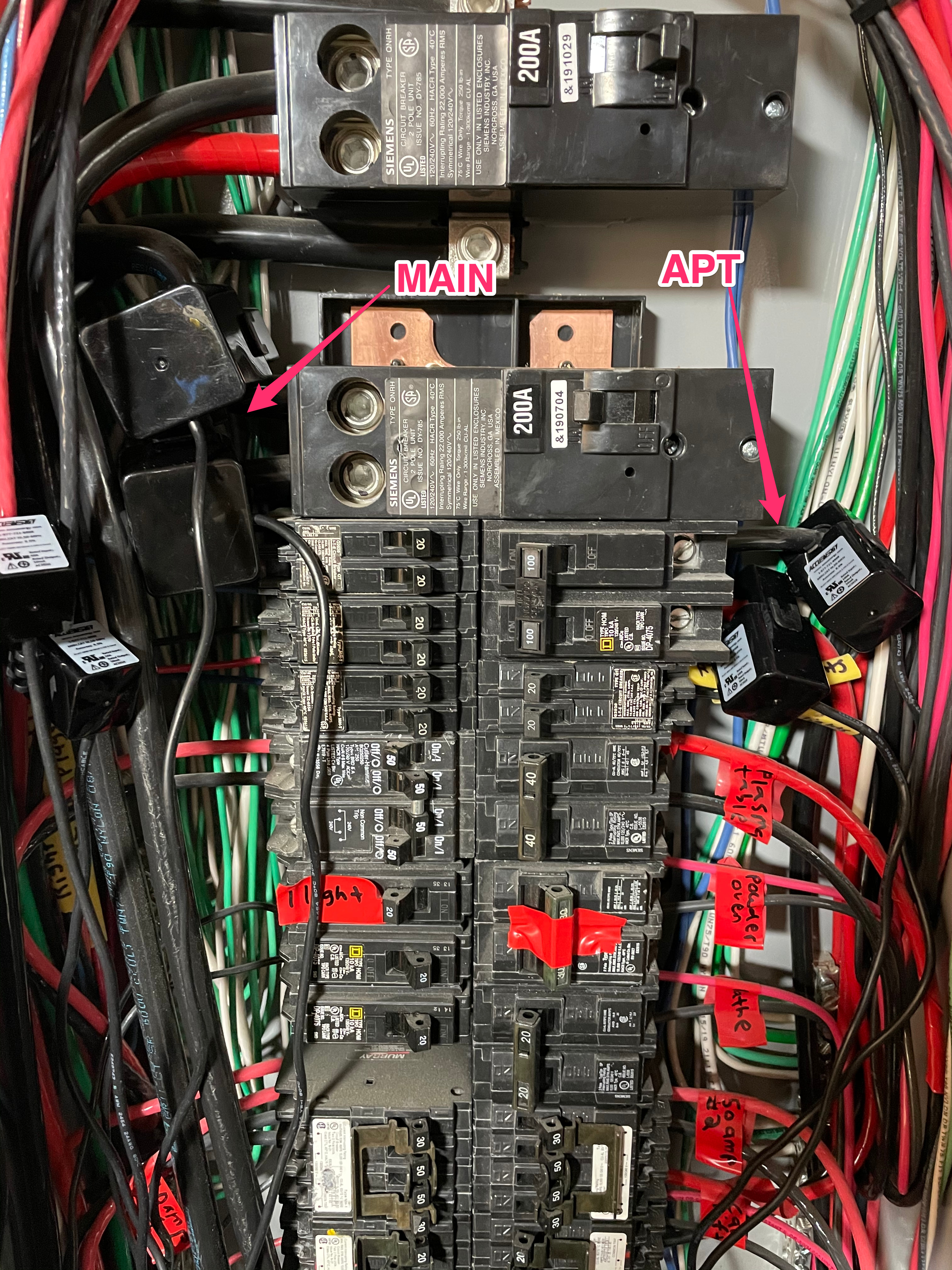
OK, can you post picture of the load-center showing the CTs as installed, and a plot of the Main_A, Main_B, Apt_A and Apt_B over the last 12 hours?
Also, please verify that you don’t have solar or other generation.
It’s very tight in there and must have been very difficult to install the mains CTs. Looking at the graphs, my suspicion lies with Main_B reading low as Apt_A never exceeds Main_A. while Apt_B always exceeds Main_B.
There are some other subtle clues. Most of the time the two legs appear to be completely independent, indicating mostly 120V variable loads. But there are a few interesting spikes at 01:00 (second one) and 09:00 where both of the mains spike at the same time. That appears to be a 240V load, but the two spikes are not equal in amplitude - Main_B appears to be about half the spike of Main_A in both instances.
It’s very hard to get a CT to read too high. Most of the time when they are off they read low. Moreover the Main_A is validated by Apt_A.
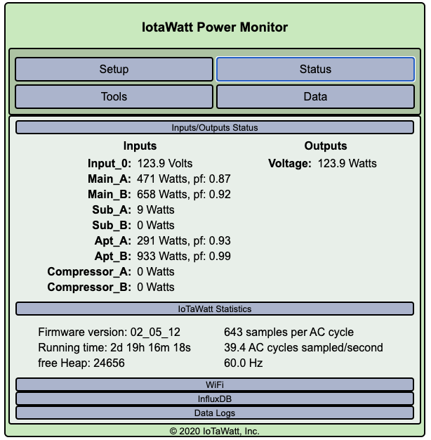
Another clue is that the power factor of Main_B in your original post is 92 where the Apt_B PF is 99. That looks like a predominantly resistive load and Main_B should have a higher PF.
All that suggests to me that the Main_B CT may not be properly seated, may have impurities between the cores, or may be cracked.
The picture doesn’t show the whole box and I can’t tell if the mains run down to the bottom of the box or out the side. I think they run down. If there is more room down there to install the CTs, I’d suggest at least moving the Main_B down there. If not, you have a pair of ECS25-200 clamp-on CTs. You could substitute one of those for Main_B to see if it resolves the difference.
Thanks - I’ll move Main_B to somewhere else to see what happens.
The mains run out the side, but I can connect the CTs on the other side of the panel.