I have recently successfully used Iotawatt to track a leak in my well water system (house and barn). I found the leak, fixed it and watched that no wattage was used by the well pump overnight (yay). That part of the graph shows zero watts. But after I started using the water again the next day, I see that there is low wattage (40-45 watts) flowing to the pump circuit even when the pump is off. I am not as knowledgeable as most posters here so I hope this is not a stupid question. I finished the repair and turned the pump back on at 22:00 last night. It then stayed at zero all night. A little after 9 this morning I started using water and you can see the pump turned on and then went to zero again briefly. After that, it was drawing that low wattage even when not pumping and I am confused by that. I see it has dropped to zero again tonight but want to understand this if someone can help me.
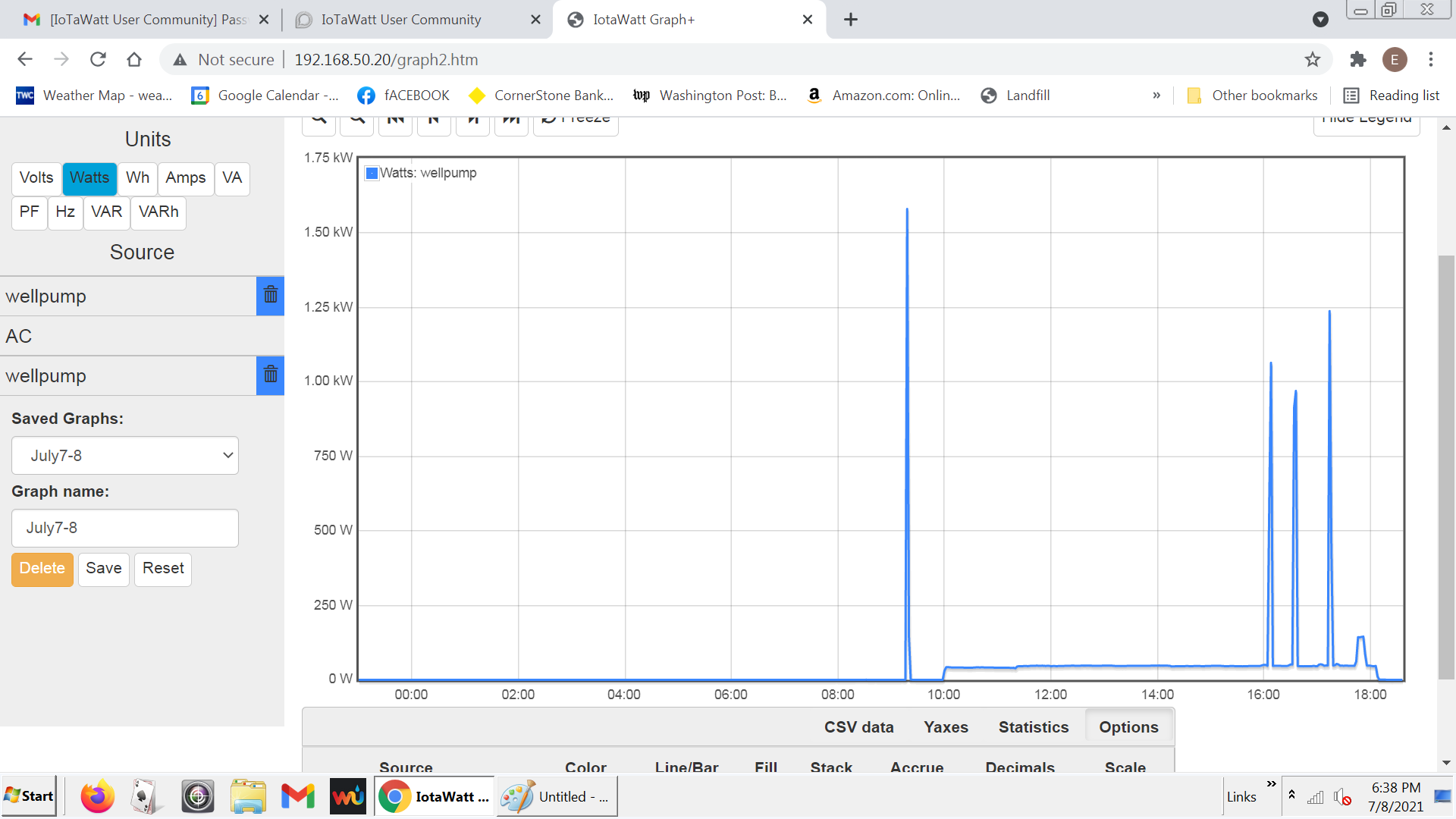
Looks to me like there is something else on that circuit. The 40W load from 10-6 is one load, but also the dimple just before 18:00 looks like another load of around 80-100W. Id find it unusual for there to be a couple of low power 240V loads on the pump circuit, so a clue might be if the pump circuit is three wire at the breaker (red and black on the breaker but also a white connected to the neutral bus) and two wire at the pump (which is what pumps usually are). If it’s not immediately resolved, keeping an eye on it for a few days may show a usage pattern that you recognize.
Okay, so watching it this morning, I see I am showing that same low
wattage (46.2 watts) coinciding with the running of the pool pump. I
also wonder if this is why my graph shows 2 well pumps and when I try
to remove one, the other one disappears too. Does it sound to you
like my wiring is wrong? (I have never made any changes to my breaker
box but contractors have). Look at the left column where you will see two “wellpump” sources.

Is there a better way than a screenshot to share the graph with this forum?
Screenshots are the best, but I see that you are posting the whole monitor screen rather than just the window or portion of window. Different browsers have different ways of doing it. It looks like you’re using Firefox. If you click on the options menu in the upper right and select “more tools”:

then “customize toolbar”
You’ll get a collection of icons that you can add to the toolbar. Drag the “Screenshot” icon to the “Bookmarks Toolbar Items” space.

Now the toolbar should have the screenshot icon
Whever you click that, you will have the ability to select exactly what you want in your screenshot. In fact it’s more than a screenshot, it’s a window shot that can select as much of the window as you need, including what may be off the sides of the screen. You can copy and paste it into the forum, or download as a png.
I digress.
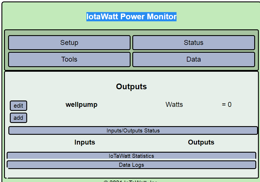
It looks like you may have two inputs defined as wellpump, or possibly an input and output defined as wellpump. Could you post your input and output setup and your status display?
Thanks Overeasy. I did not have the options you listed under More Tools (I was using Chrome on Windows 7) but know how to edit a screenshot in Paint and can do that next time. Here is my output screen:
and input screen:

I am not sure why my AC circuit is not showing up in outputs since I can get data from it for the graphs.
You have both an input and output named wellpump. You don’t need the output named wellpump, in fact it isn’t mapped to your wellpump anyway, it’s set to always be zero. So just deleting that output should make the graph+ less ambiguous with only one wellpump.
Graph+ lists all inputs and outputs that can be expressed in the selected units (Watts in this case). AC is listed and can be plotted because it is an input.
Getting back to your original question about the power used by wellpump, it does appear to be measuring multiple circuits or else your pump circuit has multiple loads connected to it. I can’t offer anything more without seeing how the CTs are installed inside your panel.
BTW, the 200A clamps are usually used on the mains to measure the whole house usage, and 50A or 100A CTs used to measure individual loads.