Just installed my second iotawatt in the ‘main’ breaker last night. Still configuring and waiting on some 3.5mm splitters but I went ahead and connected one of my heat pumps to 4 inputs.
This is the upstairs unit that does the brunt of the work (older, not the most efficient house…). I’ve been using an ecobee on it for years. Looked at the usage this morning and am trying to figure out what’s going on.
The air handler has a double 50amp breaker so I have two 100 CTs on it as I will eventually combine them using a splitter.
The heat pump has a double 30amp breaker with two 50 CTs on it that will also eventually be combined using a splitter.
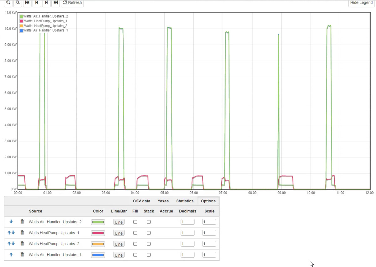
According to ecobee it doesn’t show any Aux Heat being used. Are these green spikes defrost? If so, seems weird that some of them are at the beginning of the cycle.
Looks like resistance heat strips to me. Looks like the thermostat calls for heat and the compressor starts up and tries to make a go of it but can’t cut it. So, the thermostat probably calls for “emergency heat” and 10kW heat strips come on.
To me, this looks like a controls issue. It is probably not an inverter heat pump that can modulate, but probably has at least two speeds. A smarter control might anticipate the coming demand and start the heat pump for a “soft landing” and run it up, then low speed to a “soft stop”. The net result not only uses the capacity of the heat pump to avoid the dreaded emergency heat strips, but also keeps a more constant, comfortable temperature.
Thanks Bob for taking a look. This is a 2007 unit but I don’t know much about it. Will do some digging and see if it needs configured (wiring or thermostat) differently.
16 years is a pretty good run these days! Might be time for a new, more efficient Heat Pump system. I have two systems, one about 14 years old and the other about 12 years old. The 14yo system is starting to struggle to keep up with cold nights, and I see the resistive heat strips being used more each year. It was serviced not too long ago. I am not going to put any more $ into fixing it at this point.
Great having the IoTaWatt data to confirm this. Keeping multiple years of data in InfluxDB makes it easy to visualize.
I knew it was getting up there in age but didn’t know the year until I called around today to see when the previous owner had it installed. Would love to switch to something more efficient and that may be sooner than I thought sadly.
Been mulling this over all day trying to think of what’s going on.
But regarding the data, I know with pure 240 if you using a single CT you double it. Since I have a CT on each conductor right now and each one is showing 10kw ( blue is hidden behind the green in the graph above), that means it’s using 20kw total?! Or have I been thinking too hard on this today and am missing something.
Thanks for your patience on this kind of stuff. Yes, ultimately I should just go with a single 50A doubled. Space is also a bonus.
I fell into the mindset of wanting a CT on every wire for the pure 240s. I’ve seen the light now
After seeing the heat pump (not air handler) circuit sitting at 40w, I now know there is such as thing as a crankcase heater on them. This stuff is eye opening and very interesting.
Wife just kicked on the dryer so time to learn about that…
Hey Bob - is there an easy to convey explanation on why setting the CT to the 200A version would skew the data like this? All come down to the resistors?
Sure, when a 100mA:50mA CT outputs 20mA it means it is measuring 40A. When a 200A:50mA CT outputs 20mA it means it is measuring 80A.
We call the ratio between primary and secondary the “turns ratio”. The 100A:50mA (.05A) has a turns ratio of 2000. The 200A:50mA has a turns ratio of 4000.
Bonus question: what is the turns ratio of a 50A:50mA CT and what would an output of 20mA indicate?
Turns ratio of 1000 (50/.05) and 20A (1000 x .02). I hope. Thanks!
May take me a bit but my questions will hopefully get more educated over time.
Now that things are meaning more and I have more context, going to read over the doc again.
As a fellow heat pump user (and iota user), I can say that yes, what you are seeing is exactly defrost being called for by the outside unit based on you saying the stat wasn’t in AUX/Emergency and the usage is on the air handler side. Apologize if any of this is known to you but maybe it will be informative for others. Defrost is most likely to happen between ~20-40F due to dew point temps and relationship between humidity in the air and temp…when it gets real cold the air can’t hold enough moisture to condense and freeze on the coils so you’ll actually need less defrosting then. I have also seen a defrost “first thing” in a cycle, I’m not sure why. I’ve read the manual on mine and I know there are multiple sets of conditions that will cause a defrost cycle to start.
Before I got the iota I thought that the only time the aux heat came on was when the thermostat (also ecobee in my case) called for it but that is mistaken. There’s a low voltage thermostat wire going from the aux heat terminal on the stat down to the air handler (where the heat strips are installed) and another that goes from the control board of the outside unit and those 3 are tied together. So essentially EITHER the thermostat (because you called for AUX direct, or it isn’t “keeping up”) can call for aux heat OR the outside unit can call for AUX because it is defrosting. The AUX heat is normally enabled because on a heat pump defrost is just the heat pump running in A/C mode and instead of moving the heat from outside to in it’s taking some of the heat from your house and moving it outside to the coils (you’ll notice the outside unit fan is not on during defrost because it WANTS the heat to just sit in the coil to melt the ice). The resistance heating (like a toaster, COP of 1) elements are turned on by that signal from the outside unit saying “Hey I’m defrosting…it’s gonna blow cold in the house for a few minutes” so that keeps it from blowing cold air at the expense of very high usage for a few minutes. It wasn’t until after I got the iota that I realized the outside unit can also call for AUX heat and the thermostat doesn’t “see” this at all so it’s phantom power usage unless you have a way to monitor that. The AUX heat in this case is purely used as a comfort thing because the heat pump is literally air conditioning your house for those few minutes and it doesn’t really “help” the defrost since the strips are AFTER the coil in the air handler so it heats the air right before it leaves the air handler so it has to mix all through the house before it can make it back to the coil to head outside.
We had our (older than yours) old 3T unit replaced a couple years ago with much more efficient unit that can still produce about 2T of heat at -5F outside. The old air handler had 15kW of strips and the new one also has 15kW but the contractor hooked 10 up as primary and the other 5 on a separate breaker that we could turn on “if we needed”. When our yearly maintenance was coming up the wife and I were discussing about re-configuring things a bit with the heat strips and trying to figure out what to ask him to do when I realized about the wires and just went down to the air handler and disconnected the AUX/Defrost wire from the outside unit. We’ve been running without any aux heat for almost a year now. I’m pretty sure most heat pumps even when they are at the absolute bottom of their operating range are STILL operating at a COP over 1.0 (resistance heat) so you always want that compressor running as long as the temps are good and only want to augment the heat pump with the AUX heating. Unless your compressor fails and then that resistance heating becomes your only heat source but I’d hate to see those bills. If you feel at all uncomfortable don’t touch anything, I’m sure you ask your HVAC person and have them do it for not a lot of money but I’m just tossing the idea out there as something you could try if you’d be willing to have a few mins of cool air blowing to save that electricity. It’s never really bothered us. I live in climate zone 4-moist so I’m sort of middle of the road in temp extremes.
Overeasy has already given you some thoughts on the CTs, I myself just have one CT monitoring each half of the unit and have the double box checked since they are pure 240V circuits. You can easily pull 2 of those to use for other circuits.
I’m guessing you either live in a milder climate than me or have a small unit. As I said I had the air handler + 15kW strips on a 100A breaker since you have a 50A you might only have 5 or 7.5kW of strips but I’m guessing 5 based on your reading of 10kW and having your setup a little off.
I also love that you’ve figured out the wonderful existence of the crankcase heater with the iota. Mine is only 25w. I got a buddy of mine to shut off the breaker of his A/C only unit over the winter.
Great reply! I always like posts that start with tldr
I knew about the heat strips turning on to counteract the defrost but that’s fairly recent knowledge I obtained when I was rewiring my other air handler last summer. Really glad you pointed it out though because if I hadn’t of done that work, I also would have still been thinking they were only for thermostat-controlled aux mode.
This is all very interesting stuff and the iotawatt combined with the ecobee really gives you a full picture. Blessing and a curse!
Really appreciate your reply. I know mine isn’t doing it full justice but my break is about over.