200 amp 4-pull CT's for all-in-one

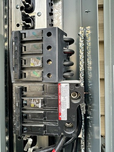
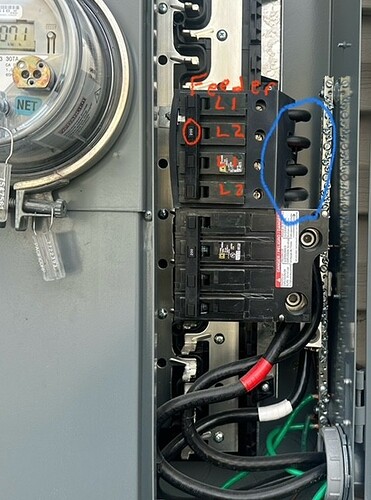
I have a square D all-in-one w/meter. It has a 4 pull 200 amp which feeds the panel. Metering here with CT’s would be the best spot. However its very tight and any split CT won’t fit. The wires are very rigid. The other side is tied with tamper proof seals from the power company.

So my thought is to use 4 small CT’s. L1/L2, L1/L2 one for each leg. Being a 200a breaker. Would 4-100 amp CT’s work? I expect each leg/pair are 100 amps.

Also any recommendation on which CT’s to use?
I found these on Amazon ETCR50FA Flexible Coil Current Transformer AC Current Transformer Coil Current Sensor. Emporium has a similar option they use.
[Current Sensor, ETCR50FA Flexible Coil Current Transformer AC Current Transformer Coil Current Sensor AC Current Transformer Probe Probe Accessory for Electronics Industry: Amazon.com: Industrial & Scientific](https://ETCR50FA Flexible CT’s )


To answer your direct question, that Rogowski coil would require an integrator. You can use the Emporia Rogowski coil with IoTaWatt. They come in a set of two with an integrator and power supply.

That said, it looks to me as though the panel you show combines the 2xL1 and 2xL2 lines into single lines coming out of the 4 pole mains CT. You could probably get 200A CTs onto those.

Above you appear to have added a solar inverter. Not clear if you added 2x100A inverters or a single 100A inverter with doubled L1 and L2 lines.

Either way you should be able to put 100A CTs on those lines or 50A if they are 10mm or less in diameter and it is only 1 100A inverter.

When the lines are doubled, the current is divided between the two but not always 50/50, although usually close to that.

By measuring the mains and solar, you can get the net grid usage by creating an output that subtracts the solar from the mains feed.

The 4-pull 200 amp feed breaker. Is black L1, red L2, black L1, red L2. I don’t think I can get every other wire but if the CT’s are really flexible maybe.
So the emporia ones will work. I was curious on that. I did see they had other boxes and power, but had no clue what they were.

The inverter is my new add. 2-100 amp breakers that feed the inverter.
The inverter is located in the basement with my main panel. Which is near my Iotawatt unit. I can easily connect those leads down there. The other are the main 200 amp service going through my Enphase 2 switch (with combiner and 2-3k batteries) then it feeds the whole home panel.
The Enphase and new inverter doesn’t see each other and don’t play well with each other. They both get power and backfeed here.
My new inverter currently only charges and discharges my new batteries. Trying to setup a self consumption system. To minimize grid feedback and use more of my power.
So I am hoping to use my iotawatt to see any back feed. Then in home assistant match the back feed to charge the battery. Then discharge as I need power.
That is the hope lol

“Either way you should be able to put 100A CTs on those lines or 50A if they are 10mm or less in diameter and it is only 1 100A inverter.”

An I use 50 amp CT’s on a 200 amp breaker if it’s in 4 legs? Or would it need to be 100 amp or 200 amp?
Not sure on a 4-pull breaker

Since I have 100 amp CT’s with my kit. I can see if I can get them to fit. If I can get 2 to fit. Would it be best on the L1’s or L2’s on each line of 4? Or 1 of each top (L1) and bottom (L2)? Then double the numbers.

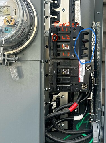
I can’t see the whole panel in the photo, but it looks like there are three four element breakers there.

If I read it right, the four element pull breaker is the middle one with black cables turning sharply out and back toward the meter. It feeds current to the two busses.

The lower 4 element breaker appears to go to your main panel. The L1 and L2 elements appear to be combined into single L1 and L2 lugs to which the feeds to your main panel (via Enphase) are connected and go out the conduit in the lower right. So that breaker feeds 200A into each of the cables to your main panel.

Not sure why you have a 200A breaker to backfeed the 100A inverter, but as you say you can access that feed in the basement near the IoTaWatt. Hopefully there is a 100A breaker at the inverter, otherwise the inverter appears to be exposed to 200A from the Grid.

I don’t have any info on the enphase battery unit, but you will probably want to measure both sides of that with 200A CTs. If you can do that at the Enphase unit, I don’t see any need to put any CTs in the SquareD panel. As long as you are monitoring the inverter and the feed line from that lower breaker at the enphase, you have all the data that you need to compute Grid (meter).

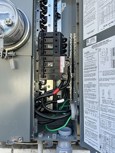
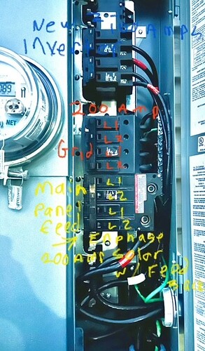
This is the panel before I added the 2-100 amp breakers.


Weird, I sent a reply but it didn’t save it. I posted the images after the response.

I will try to recall it all lol.

Yes, The middle breaker feeds the busbars. The 4 wires come from the meter/grid. The design doesn’t have any lugs on the user side. And has anti tamper tags. Where they feed from the meter.

The two 100amp breakers I added to the top. Feed directly to the inverter thru 3 gauge wire running into the basement. The inverter supports 200 amp pass through and is wired with 2-125 amp breakers built into the inverter. I wired it based on the instructions and feedback from the dealer. However a line side tap was also an option. I felt more comfortable with breakers. However hindsight I don’t believe it pulls anywhere near 200 amps.

In home assistant I can see the Enphase, the new invert (12k NHX), the Enphase micro inverters, Enphase batteries and the new battery on the NHX. And the Iotawatt. But the import/export/grid numbers don’t match what the Enphase app reports which I expect is accurate. But they likely do some calculations using the sensor data.

I am new to this and still trying to figure out how it all works. So I ask lots questions of which might have obvious answers to someone who understands it better. But I a slowly learning lol

The NHX inverter has 2 built-in breakers. That are L1/L1 the second is L2/L2. So it was easier just to wire them to two breakers.

The Enphase handles the grid interaction adding solar and batteries as needed. Then exports the excess to the grid. The Enphase doesn’t work with other inverters so it doesn’t see the NHX. They both see the other as grid and or load.

My goal is to reduce the export of power and store/self consume as much as possible.

The NHX has grid integration using CT’s (L1/L2). I have these located on the main lines coming out of his all-in-one where it enters the Enphase controller. I have also installed the 200 amp IotaWatt CT’s in the same location.

I can capture the NHX, but will need to get some more higher amp CT’s to capture what I need.

My thought is to capture the readings off this main breaker feeding the bus bars. This would give me the actual numbers coming from and going to the grid.

Then with all this data. Figure out how to program Home Assistant automation to change the NHX to match the export amount and charge accordingly and discharge/self consume accordingly. But base it on realtime sensor data.

Mind you I don’t know what I don’t know lol or how to completely accomplish it all. But the data is the 1st step. My son is a programmer (but not knowledgeable about solar). If I can’t figure it out I am hoping he can help.

But I appreciate any input and inspiration from others.

Currently I am able to do the above by checking the Enphase app and remotely changing the settings on the inverter to change and discharge the NHX. But manually is no fun lol

Currently have Iotawatt CT’s on solar output (240v L1/L2) and Enphase battery L1/L2. But on 1leg each with the double checked for 240v. Then the 200 amp main CT’s power coming out of the meter box. I have the 100a CT’s and all the other 50a ones. Which I can deploy where needed, but I think I will need more 100a ones and possibly the flexible ones for the main breaker in the panel. Unless I can figure out another option.

I would need a line drawing of what you are trying to describe in order to comment any further.

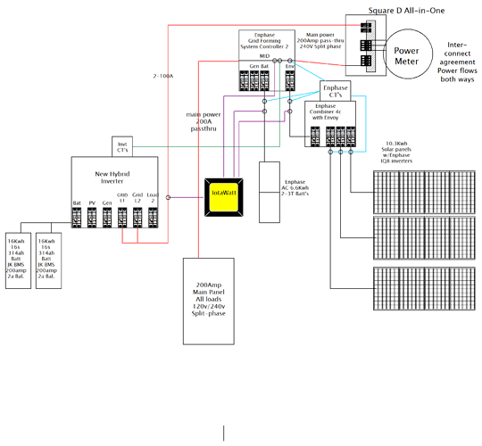
Here is a basic line drawing without the CT in the Meter box all-in one.
All lines are Split-phase 240, except the battery to inverter and CT’s.

The little circles are CT’s

Since neither system see’s each other directly. Capturing the main leads in this panel would give the real import/export readings. Not looking for a net amount. I have a Net meter but I am not charged based on the net. I am charged by the amount of power I use. Then I am paid 50% of retail on what I export. My goal is to use more of the power I create and send less to the grid.

1 Like

UPDATE: This is an update of an earlier proposal that turned out to be more complicated than I first thought, incorrect and inconsistent.


You appear to have the makings of all of the data that you need to monitor this system. There are several elements:

The All-in One panel is the service entrance where the GRID is connected to two other elements: the NHX inverter and the Enphase Grid Forming System Controller. There are three connections:

GRID - the incoming utility service
NHX - the connection to the NHX inverter
ENPHASE - the connection to the Enphase Grid Forming System

Moving down, the ENPHASE has four connections:

ENPHASE - the connection from the All-in one Panel
PANEL - the load service panel
BAT - the AC coupled Enphase battery
SOLAR - the solar array output.

The initial attempt to assign polarity to these connections did not work in hindsight. For instance, the ENPHASE line between the All-in one and the ENPHASE unit is both a load and source depending on whether its with respect to the All-in-One (load) or ENPHASE (source). So making it + or - is somewhat arbitrary. The important thing, i think, is to be consistent and define the relationships. So here goes.

First let’s look at the NHX inverter. Basically, as configured in the line drawing, it’s the same as the Enphase AC coupled battery. You can add PV and a generator, and it starts to look more like the ENPHASE Grid Forming Controller, but right now it seems to look like the battery. So let’s monitor them the same way:

  • NHX and BAT should both be positive when discharging and negative when charging.
  • SOLAR should be positive when providing power.
  • PANEL should be positive

All other metrics are done with IoTaWatt outputs using those four inputs.

GRID = PANEL - SOLAR - BAT - NHX
ENPHASE = PANEL - SOLAR - BAT

Combined battery discharge = (NHX max 0) + (BAT max 0)
Combined battery charge = (NHX min 0) + (BAT min 0)
Net battery discharge(+)/charge(-) = NHX + BAT

So what needs to be resolved is if the CT that you show in the ENPHASE box is measuring the grid gonnection or the panel connection. It should be on the grid.

I suggest that you put the 2x200A CTs on the panel mains.
Assuming the SOLAR feed is two wires (no neutral) you can use one 100A CT and double.

Same for the battery I think if it’s maximums are below 24KV.

The NHX appears to be three-wire so you probably need 2x200A. They can be installed at the NHX rather than the ALL-in-One so nothing needed there.

You will need to setup some integrators to get accurate Wh. I’ll explain that in a later post.
This is great information, thankyou!

Enphase Controller:
Currently I have the 200 amp mains clamps on the L1/L2 cables feeding the power to the Enphase controller (from the all-in-one). Allowing neg/ pos. This is Grid in/out.

Enphase AC Battery:
I then have a 50 amp on L2 for the battery line going to the Enphase controller. This has a 40 amp breaker. I have this set to double and allow pos/neg.

Enphase AC Solar:
then have a 50 amp on L2 for the AC solar coming into the Enphase controller. This has a 30 amp breaker. I have it set to double but only positive.

NHX Inverter:
This is fed with 6 wires (L1/L2/N/G) x2) from the All-in-one from the 2-100 amp breakers. I have the 100 amp CT’s each L2 going to the Inverter. I have these set to double and pos/neg. Currently it is only used to charge and discharge the 2 new batteries. We can call these eel_batteries

Main load panel:
The 1 connection I don’t have is the 200 amp in my panel. I will need to get 2 more 200 amp CT’s to accommodate that.

Neutral wires:
I will need to double check the Enphase battery and solar if they are just L1/L2 &ground or if the have a neutral. The Neutral and ground are bonded in the all-In-one. Then the rest of the house has the neutral. However I recall the Enphase batteries didn’t need one of the wires which might be the same for the solar.

So I guess if that is all correct then all I need are 2-200 amp CT’s for the panel and the rest is programming. I will put the on order asap!

Thank you so much! This was making my head spin lol

You don’t need those. You can move them to the panel mains.