I’m using a 3-phase 230V system with three independent voltage references. One of the phases (T) has false readings quite frequently, sometimes only a spike, sometimes over a longer period of time. What could be the reason for this?
You probably have your reasons for thinking it’s a false reading, but I have no basis for making that assumption. What makes you come to that conclusion?
I made some manual measurements some time back and also replaced one of the reference voltage generators. Did you ever encounter anything like this? What I can do here is that since I have a home automation system in place, I’ll put an alert on values that are unlikely low, and I can make manual measurements again just to be sure.
The easiest thing would be to just swap that VT to a different phase and see if the problem moves with it.
Sure, I’ll try that.
I swapped reference inputs 7 and 14 that are configured for two of the three phases (0,7,14) and the problem remained with the phase whose reference input is at 14, it did not move, therefore I assume the input is wrong somehow.
If I understand what you are saying,that should indicate it’s not the transformer, but not ready to say it’s the input at all.
How is it that you are using input 7 for a VT? The V5 unit uses 0, 13 and 14?
When you swapped the VTs what exactly did you do? Did you swap the both the socket and input they use or just the socket?
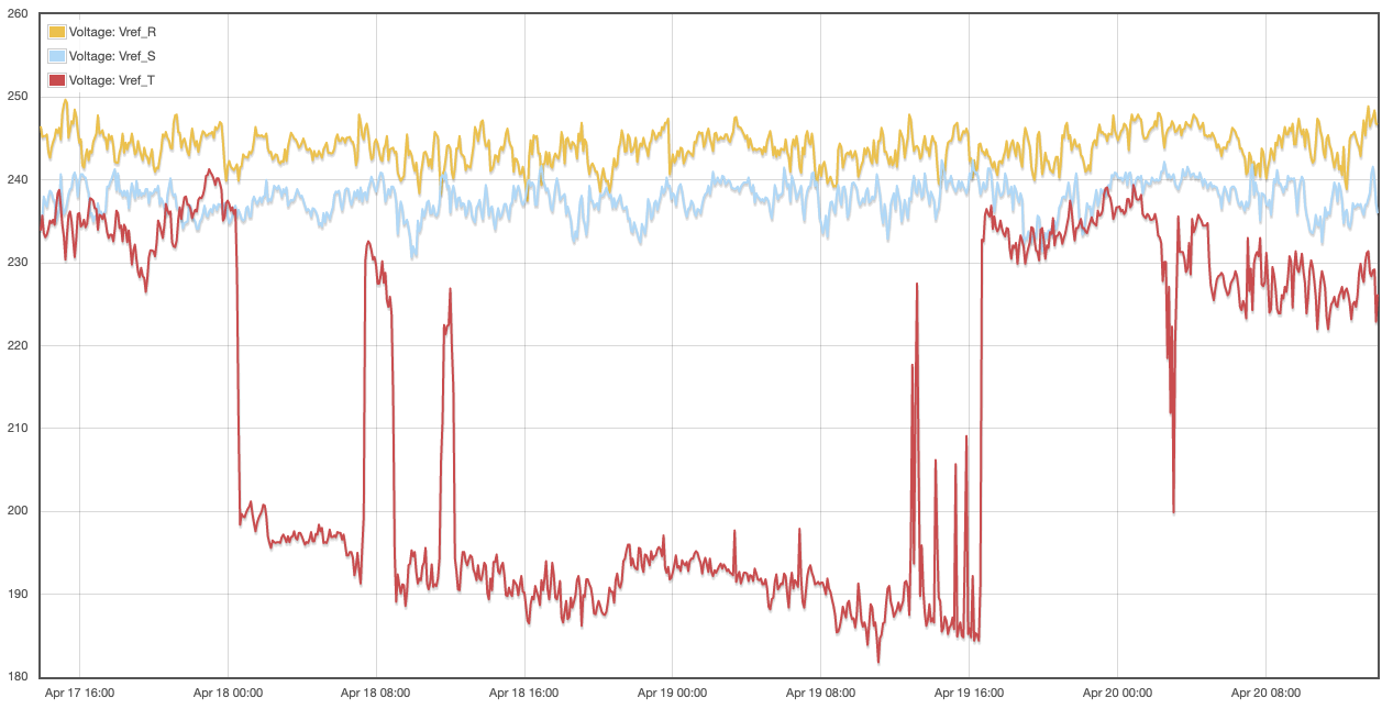
Looking at your original post, the voltage dropped to around 190 Volts for a 40 hours, then went back to normal. Have you determined that the voltage did not indeed drop?
I have a V4 unit, not a V5. Firmware version is 02_05_12. From what I see in the configuration UI I can freely configure any input as VT or CT. I just did so some years back. Now I swapped the VT plugs 7 and 14 on the device side and nothing changed so I assume the problem could be with input 14. I made external measurements again and again and the real voltage readings do not drop. I can reconfigure in a way that I relocate the VT to an input other than 14. Please advise how to proceed.
Nice. Did you think it was not important to tell me that the unit has been modified to adapt CT inputs to accept VTs? What could possibly have gone wrong with that?
Yes, you can configure any input to be a VT in the software, but you can’t directly plug a VT into them. Prior to the V5 there were several methods being used to adapt the CT inputs for VT use. They all required using resistors and some involved removing the burden resistors. Some dissipated a lot of power, some did not. Some incorporated the built in burden resistor, some did not.
So you would need to elaborate on the modifications used to adapt the VTs to the inputs. It’s possible that damage was done, but I think more probably that there is a bad connection or solder joint. I can’t speculate any more than that without seeing what you have.
So I would need to know what kind of modifications you made to adapt the VTs to the CT inputs.
I did not modify anything, but when I ordered it from you, you sent me two special cables that already contained the burden resistors. I just plugged them in. Shall I then examine the solder joints on the two supplied cables?
OK, fair enough. A couple of years ago prior to the V5 I provided a few users with custom cables to do that, and I also made some adapter boards that did the same. There were several different methods used. I don’t recall making up your adapters or how they were constructed.
Figuring this out should be straightforward, but it involves understanding the components in play (now includes adapters), and exactly what is being done.
Does this mean that you swapped the VTs with their associated adapters, or just the VT leaving the adapters in their original inputs? In other words did you (respectively) swap the 3.5mm stereo jacks or the 5.5mm barrel connectors?
I left the whole cable intact, I just unplugged the two 3.5 mm jacks from nr. 7 and nr 14 place of the device, and plugged them into the other’s former place (swapping).
Ok, since you can use any input, next thing is to move the VT in 15 to another input, preferably 1-6.
I was away for quite a while for personal reasons, but I’d like to go on fixing this problem of mine. There is no “15” in my device, but there is a “0” according to the web GUI, and the third VT is there. I already swapped the other two VTs a while ago as you asked but I did not reconfigure the corresponding inputs to use the swapped VTs. Shall I go on swapping the thrird VT at “0” with some other slot?
I’m now on patch level IoTaWatt 4.x, Firmware version 02_07_05, and recently I started to get some strange errors and restarts:
** Restart **

SD initialized.
7/13/22 11:48:13z Real Time Clock is running. Unix time 1657712893
7/13/22 11:48:13z Reset reason: Software/System restart
7/13/22 11:48:13z Trace:  1:3, 1:1[14], 1:2, 9:0, 9:0, 8:4, 8:6, 8:8, 8:9, 1:2, 1:3, 1:3, 1:6[1], 1:6[2], 1:6[2], 1:6[3], 1:5[5], 1:6[4], 5:0, 5:2, 1:6[6], 1:3, 1:3, 1:6[1], 1:6[2], 1:6[3], 1:5[21], 1:6[4], 21:0, 21:1, 21:10, 21:10
7/13/22 11:48:13z ESP8266 ID: 2871426, RTC PCF8523 (68)
7/13/22 11:48:13z IoTaWatt 4.x, Firmware version 02_07_05
7/13/22 11:48:13z SPIFFS mounted.
7/13/22 13:48:13 Local time zone: +1:00, using DST/BST when in effect.
7/13/22 13:48:13 device name: iotaw0
7/13/22 13:48:13 HTTP server started
7/13/22 13:48:13 timeSync: service started.
7/13/22 13:48:13 statService: started.
7/13/22 13:48:14 dataLog: service started.
7/13/22 13:48:15 dataLog: Last log entry 07/13/22 13:48:10
7/13/22 13:48:18 historyLog: service started.
7/13/22 13:48:19 historyLog: Last log entry 07/13/22 13:48:00
7/13/22 13:48:21 WiFi connected. SSID=TVL9-UN, IP=192.168.1.96, channel=6, RSSI -61db
7/13/22 13:48:21 MDNS responder started for hostname iotaw0
7/13/22 13:48:21 LLMNR responder started for hostname iotaw0
7/13/22 13:48:21 Updater: service started. Auto-update class is MINOR
7/13/22 13:48:37 Updater: Invalid response from server. HTTPcode: -11
7/13/22 13:52:57 Heap memory has degraded below safe minimum, restarting.
No, my mistake, I think I meant to say 14. Reading back on the thread from 17 months ago, the problem appears to be with input 14. That could be something with input 14 specifically, or with the associated ADC which could affect inputs 8-14. Since the VT in input 14 worked OK in input 7, I would move it to one of the inputs 1-7 if available.
Not enough information to speculate on the single heap memory restart. Would need to see a lot more of the message log.
So now I started all over again. Unplugged most cables and plugged them in again. Restarted the device by removing power chord. Volt readings are fine for now. Both cables you supplied with 300 ohm burden resistors are hot at the spot where the resistors are. Restart was clean, nothing wrong in the logs. Opening screen says: Configuration not found. After few minutes, this message disappears. Some watt readings are positive, others are negative, although there is no solar production (it’s dark outside). I have no clue why.
The voltage problems reappeared shortly after restart, as seen in the screenshot, but only for the phases, whose reference voltages are connected with the special cable (7 and 14).
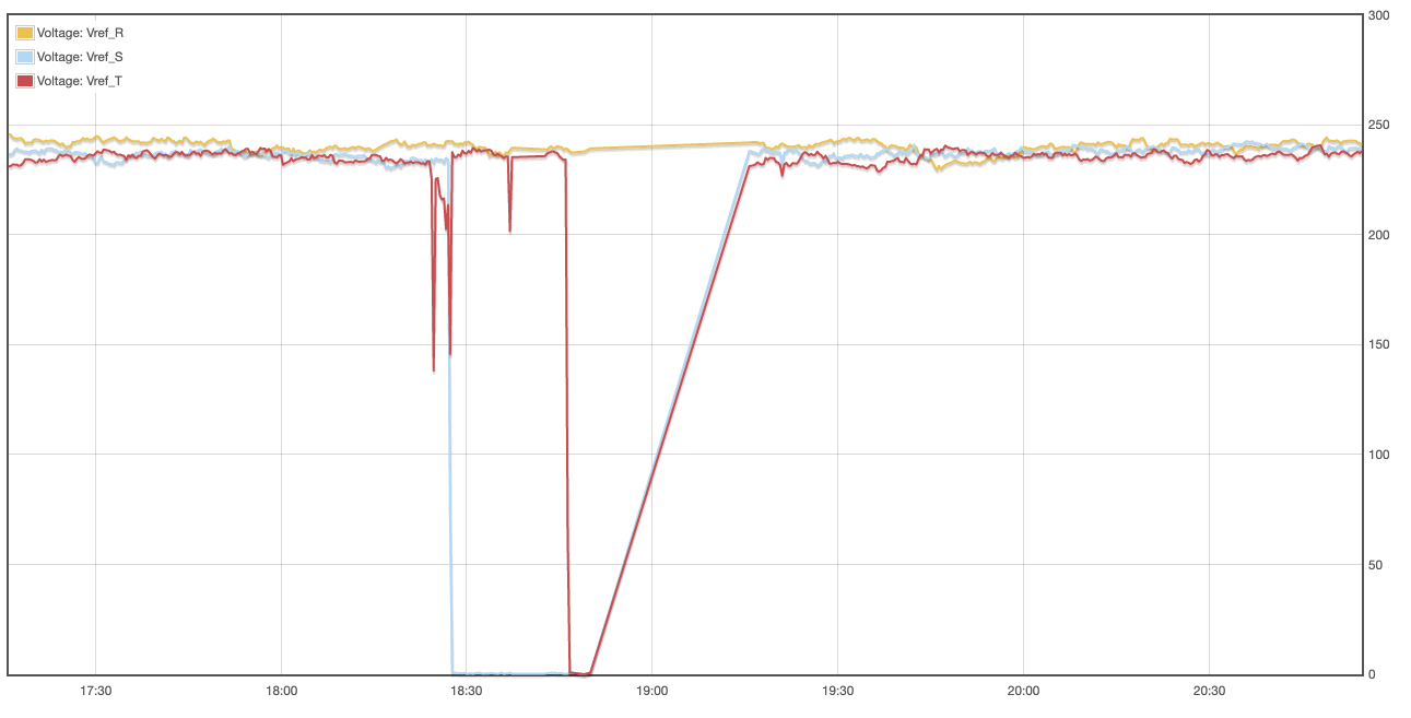
Those voltages are all about the same. My advice would be to change over to derived reference using only the input_0 voltage reference.
It changes from time to time. Sometimes they are almost the same, other times there is more than 15 volts difference between them.
I have another iotawatt device with me, same version, I’ll swap the whole device and see what will change. How can I transfer the configuration from one to the other?