Another 3ph reading issues

Hi All

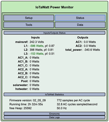
Sorry to post yet another 3ph mis-reading post but I cannot find an answer that seems to help me. I am in Australia and have a large’ish complex 3ph + solar install. I have 2x Iotawatt devices using YDHC CTs (brought them on openenergy.org site). I had them installed for about 2yrs and I noticed that they read about 20% lower than the retailers meter. In the last few weeks I’ve installed another ~26kW of solar with 3 inverters (3ph) and a 10.2kW battery. Now trying get them to report more-or-less the same numbers and its driving me crazy!

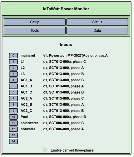
I am using the derived method at present as within a few % would be fine. I have been through the docs and finally understood that the phase the VT is on becomes phase A (in my case thats actually phase B) and then each sequential other then becomes B & C (I think). So for me A=C, B=A and C=b (real-derived). I am sure the mains CTs are all oriented the same way but I just cannot get sensible data out of it.

MDB

Iotawatt-1

Iotawatt-2

I see so many questions about this it deserves a YT video to save Bob going crazy! All help appreciated.

Cheers
Bruce
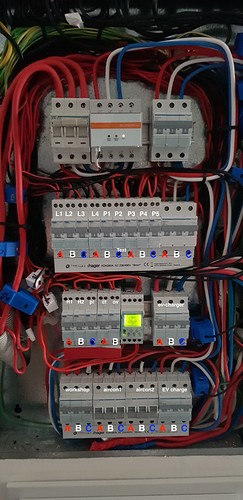
Hi Bruce,

With solar, it’s hard to know what to expect in those status screens. You have a better context, so if you are doubting the numbers, I’ll assum it’s probably wrong and start at the beginning.

First thing is to sort out the terminology. It might be clearer if we come up with something a little less ambiguous than this:

When I look at the picture, I see that the electrician observed a color coding convention of Red-White-Blue. That might be a better way to refer to the physical circuits. We could also use the positional terminology of L1, L2 and L3. So I’m going to go with L1, L2 and L3 because you already have your mains labelled that way, but the colors will be useful for configuring branch circuits where the convention has been observed. So to reconcile R=L1, W=L2, B=L3.

With that set, I’m getting from your explanation that the VT is probably on L2 and I see that is IoTaWatt phase A.

The picture does not show enough detail for me to verify that the mains CTs are all oriented the same. You should double check that, as going forward, everything will rely on that being the case.

In the status I see that L2 has a credible value and power factor. What I see on L1 and L3 is not impossible, but to be negative would require solar export, but the power factor of L3 doesn’t look like solar export.

So I’m going to suggest that we take a baby step here and get back to basics. I recently posted the procedure for sorting out three-phase derived reference mains.

I recommend either shutting down the inverters or doing this at night. Also, try to get a fairly high power resistive load for use in the procedure. It appears you have plugs on all three phases, so you should be able to do this fairly easily. You will also be able to verify the phase that you have noted in the picture for each of the plug phases.

Once that is done, the solar inverters appear to have color coded phases, so it should be easy to follow through with assigning the proper phase as determined at the mains.

I would just say +1 for the article Bob has linked to - made a big difference for me the other week when i was sorting out my IOTAWatt.

I would also suggest you label each of the phases as Red/White/Blue as it is much easier to follow

Craig