Greetings all. Brand new to this forum and energy monitoring in general. I have a utility-fed 400 amp service in North Carolina (2 x 200amp main panels), a relatively recent Generac 22kw back up that ties into one of the main panels, and a just-completed PV installation (2 Solar Edge inverters/21 kw total) that will have battery storage in a few months when the 3 Tesla Powerwalls arrive. The PV system feeds both main panels with net metering back to the utility. I am considering Iotawatt as the means to get a clear and consistent picture of:
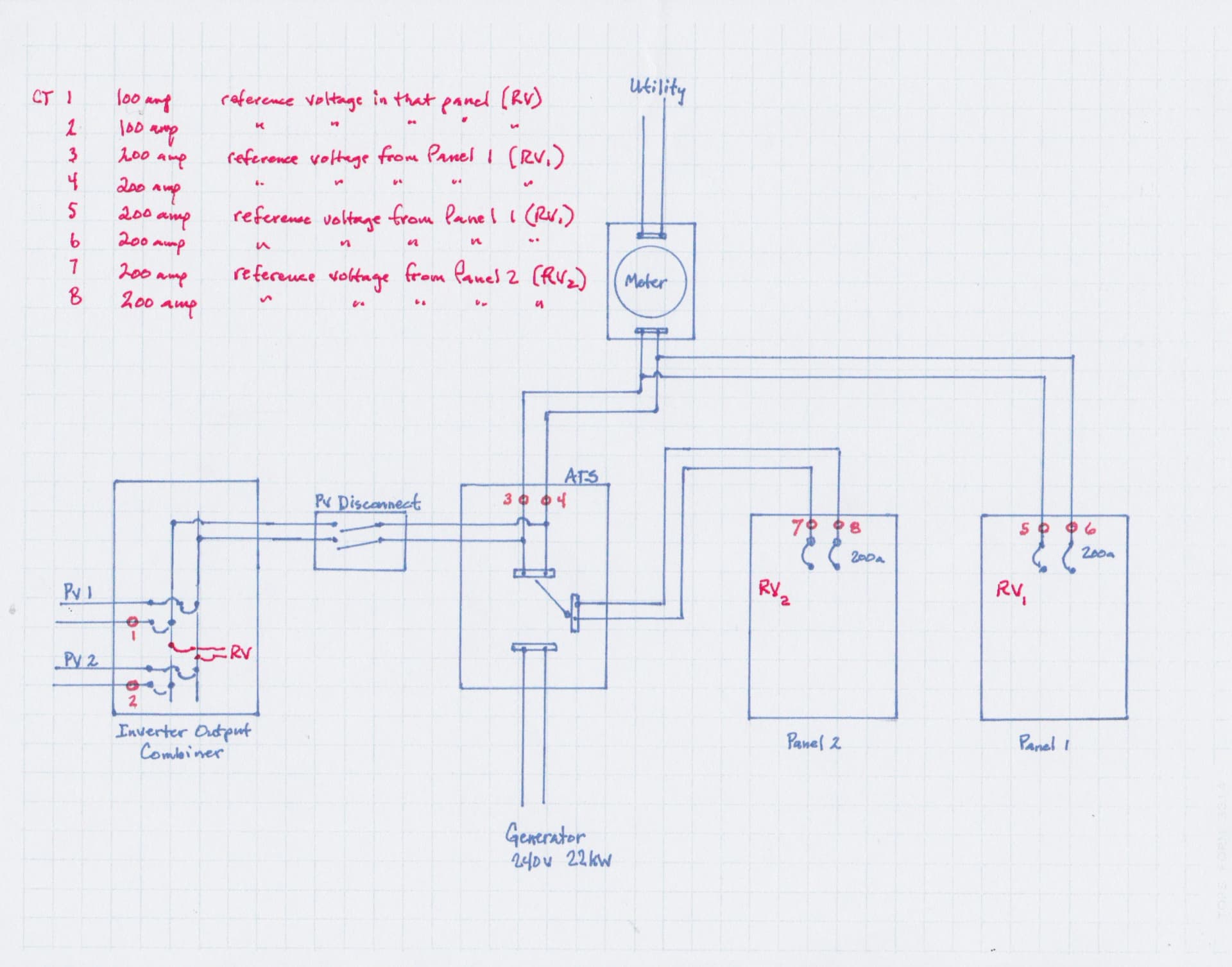
a) Inverter output current (CT on a leg from each) A check against the app from SolarEdge or for use if that cellular connection to them is lost which has happened a couple times already
b) ATS flow-thru current paths (CT on leg from Utility, CT of each leg from Generac, CT on each leg going to 200 amp panel) Should show me amps from utility and contribution from solar, or amps from solar to panel load plus amps flowing in reverse to utility, and finally when grid/solar are down, amps from Generac to 200 amp main panel.
c) amps flowing to and from the Tesla Powerwalls thru the Gateway device (CT on each leg of the battery bank connectors). Should give me amps when charging (pos) and discharging (neg). I am supposed to have a fancy Tesla app for that when all is said and done but there may be times when it’s not communicating with the mothership.
c) amps on each of the 2 panels (CT on each leg in both panels) to give me a picture of house load demand between those panels
d) amps on select variable circuits within the 2 panels to help me visualize and manage those loads during a grid down scenario when I’m relying on either batteries or the Generac
Sound reasonable for Iotawatt utilization? I would use all 14 inputs
The distances involved between some of these components will mean I’ll need to add extensions to the 5ft leads that come with each CT. Assuming I can find a proper jack-type extension cable would this be a problem for some reason? The alternative is simply to splice an extension section into the ones that needs it (soldered of course). I’ll need to select and order the correct CTs for each of these applications. I presume the Iotawatt hub can handle multiple larger CT inputs and isn’t limited to just 2 primary inputs at that size (200a)
Any responses/insights/ideas are most welcome
Thank you!