Extending CT leads with commodity extensions

Most of the CTs come with a 1.5m (~5’) cord with a 3.5mm stereo jack. There is regular interest in extending these for various reasons.

  • Shorter extensions are used to facilitate connections where the IoTaWatt is near, but not close enough for all of the CTs to connect.

  • Longer extensions are used to connect CTs from remote locations.

I have long advocated for the use of commodity headphone extensions for both of these applications. Many have sourced them and with the exception of one user who got defective extensions (crossed connections), there have been no negative reports.

CTs produce a current proportional to the primary measured current. They push this current, regardless of resistance, to the extent that they have the power to do so. IoTaWatt inserts a 20Ω ballast resistor into the circuit. The standard 1.5m lead on the CT is about 0.3Ω. The primary consideration with an extension is that it does not increase the resistance to the point that the CT cannot push a proportional current, and secondarily, that increased resistance may increase the phase shift significantly.

What I found was that the shorter commodity extensions can add resistance, although not a deal-breaker up to about 12’

image

All are slim and supple, and produce the same results compared to a control CT connected to the same circuit without an extension.

I tested a 50’ from MyCableMart and although it seemed to work, the resistance was very high at 42Ω. I would not recommend it and will continue to search for a source for longer extensions. Most users have opted to adapt CATn wiring for long runs. Perhaps a RJ45 - 4 x 3.5mm jack adapter would be a better way to go for long-haul.

2 Likes

FYI, I purchased a couple of these 12ft extensions from Monoprice which seem to have worked well. Admittedly I haven’t done the level of testing that Bob does, but looking at a 60w light bulb on a circuit with and without the extension didn’t seem to make much difference at least at the granularity I cared about.

Good price. I tested some 3’ that appear to have the same connectors. Resistance was very low so better gauge of wire. Only downside was that the male connector is larger than 11mm in diameter, so can’t plug in two side-by-side. Sometimes (often?) the pictures don’t match the product exactly, so maybe not the same manufacturer.

Hey all,
I just taken delivery of my new IoTaWatt here in AU a few weeks back, and now my solar is installed, I’m looking at getting this going.

As my meter board is outside and pretty packed full, I’m going to have to run my IoTaWatt in the shed, about 2m away- and run a conduit to the meter board.
I’m thinking I’ll run either a 4x cat5 lines (16 pairs) or 6x cat5 lines (24 pairs) to cope with the 28 or 42 wires needed for the CTs, with a little breakout box with 14x 3.5mm sockets to plug the CTs into.
I notice that the CTs have stereo plugs, but the circuit diagrams for the IoTaWatt seem to indicate only two of these pins are connected - is this just using the Tip and Sleeve (same as a mono) plug, and ignoring the ring, or is there something fancy going on that I need to be aware of?

Open to hear all thoughts, suggestions, etc :slight_smile:

Cheers
Mike

Tip and sleeve is correct.

Some have used CAT wiring with success. Also see this post about standard headphone extensions.

1 Like

Perfect, thanks for the clarification overeasy; greatly appreciated. I’ll have a go at fitting it in the next week or so and see how it all fits together.

And if DYI - what kind of AWG should I use? 24?

Hi @overeasy ,

Sorry to revive a topic that I’m sure you feel like you have addressed a number of times over the years, but there is some fundamental knowledge I don’t have (in particular WRT resitance) that I’m hoping you could assist with.

I have my IoTaWatt unit very close to (directly underneath) my main switchboard breaker box, so the majority of my circuits are happily monitored with these 1.5m SCT-013-000 CTs. Like a number of punters who have raised this kind of question, I have a sub-board on a separate building at the back of my property that I’d like to be able to get some CTs into.

The back building with the sub-board contains my home office, and in order to network the office to my main house, many years ago I ran 2 lengths of cat6 cable from one building to the other (I forget the exact cable length, but each would be less than 30 metres long). The cables happen to run right past the main breaker box where the IotaWatt lives, all the way right past the sub-board containing the circuits I want to monitor and into my office. I’m trying to work out how easily (or otherwise) I would be able to hijack 1 length of cat6 to act as an extension for the CTs.

The home office building also provides the roofspace for my solar system, which has 2 inverters that live just above the sub-board. For this setup there are 2 lengths of conduit running from the inverters to the main box, one housing a 6mm electrical cable for the Solar Feed, and the other a network cable for the solar meter in the main box (which reads the 6mm cable using its own CT) to communicate with the inverters. The cat6 cables I ran are in 20mm PVC conduit for the entirety of the outside portion of their run, and are separate from any other electrical cables (at least a couple of metres away from the inverter conduits for all but the very ends where they get close, but are still physically seperated by their respective conduits).

The Cat6 cable that is already in place was decent at the time, and easily supports gigabit ethernet speeds, but is unshielded. For reference it has “CMX Category 6 24AWG 4PR verified (UL) CAT6 ANSI/TIA-568-c.2 0004m 0316” printed on the jacket. I’m aware that running electrical alongside data cable is a bad idea, but I’m unsure exactly how close (and for how long) the cables need to be before this presents a problem. What I do know is that I haven’t been able to detect any performance impacts to the network since the Solar setup was installed.

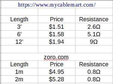
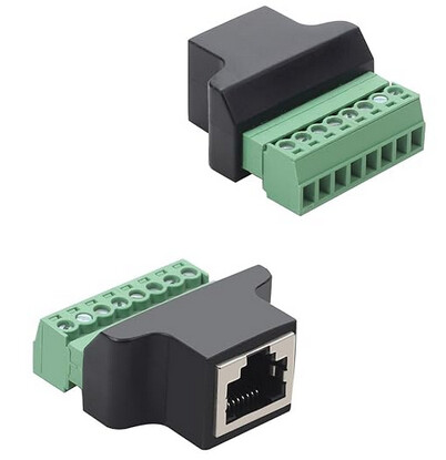
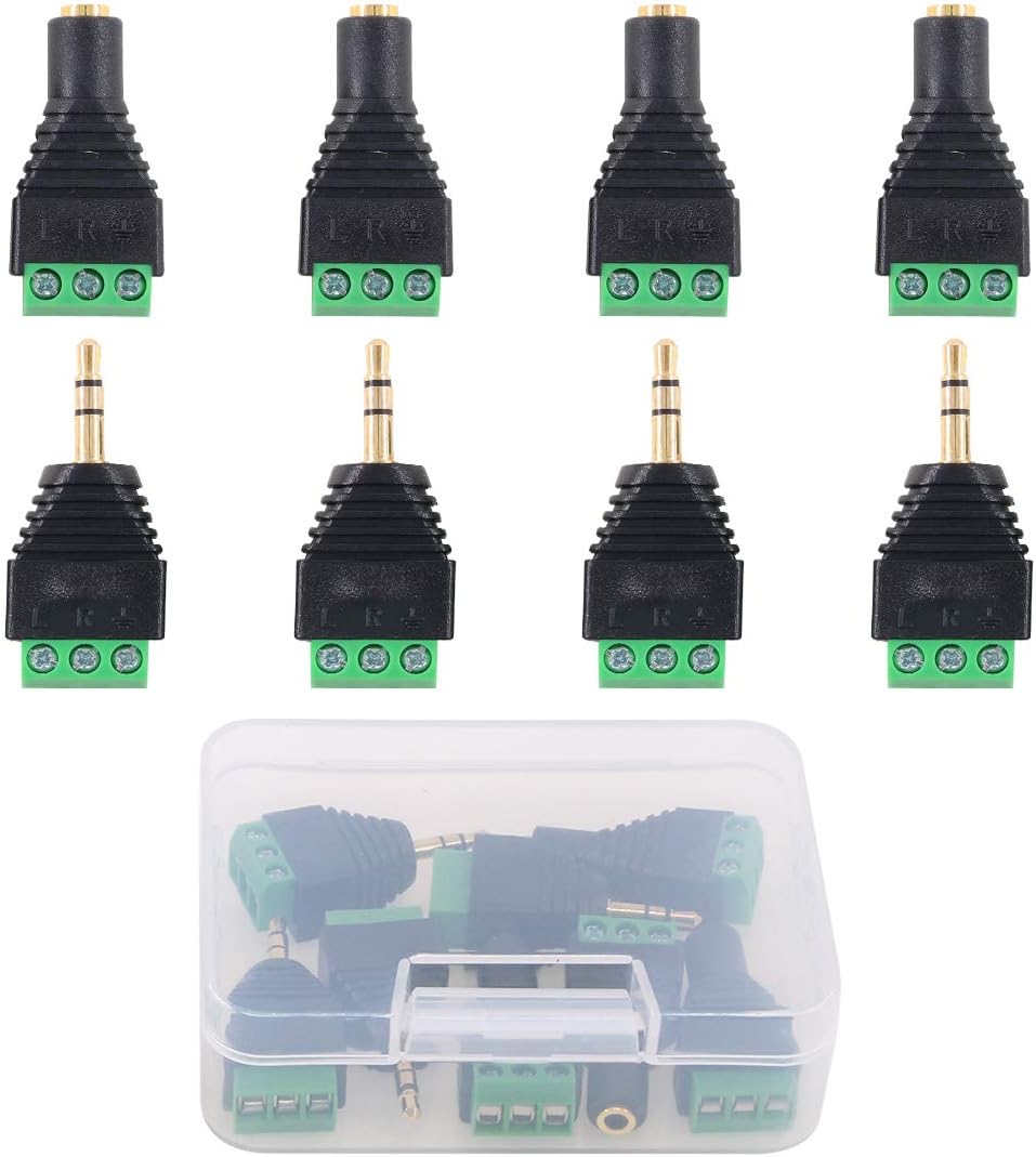
I was considering soldering 3.5mm jacks like these and these to the solid core wires in the cat6, hopefully using (up to all 4 of) the twisted pairs in the cat6 as an extension for a separate CT, so the one length of cat6 would effectively extend 4 CTs.

I have read every thread/post/comment I can find which touches on this subject (most notably this one and
Long CT extension leads and transformer type which many of the other posts point to anyway). From what I can gather, in general it seems to be assumed that cat6 should work well as an extension, but when the conversation starts to rely on knowledge of the current each CT pushes and the relative resistance of different cables I admit I get lost.

If I do proceed, I’ll certainly be trialling and testing it with cable that is not already part of the infrastructure, though the test cable is identical, having come from the same spool. Before I try it though, I’m just trying to get an educated opinion, given the setup I’m working with, on whether it’s obviously a waste of time to someone who knows more than I do, or whether it’s at least worth a try.

Any advice or opinion you can share would be appreciated. Assuming I do give it a go, I will definitely report back with the outcome and any relevant findings.

Cheers,
Pete

The SCT013-000 have a pretty high VA output. 30 meters of 24ga copper should be OK. Simple enough to try it out.

That’s good enough for me! I’ll give it a crack and report back with anything interesting.

Honestly, anything more optimistic than “Dear gods, no! That would almost certainly trigger your immediate death!” would probably have been sufficient for me to justify some experimentation, but I do very much appreciate you responding.

At least I know it’s not a blindingly obvious waste of time to everyone more knowledgable than me!

Thanks!

P.S. Would you could anticipate any problems or pitfalls attempting to use all 4 twisted pairs to extend 4 CTs on the 1 cable? Just because it’s unshielded cable and I don’t know enough to know how much interference or crosstalk it may generate, nor how much would be problematic.
Again for the initil trials I’ll likely try it anyway, if only to stress-test it and see if I find a boundary, but if you have any thoughts or opinions they’d be welcome :slight_smile:

I can’t point to a specific report, but it seems to me this has been done before. At one point I was contemplating a PCB with jacks and an RJ45 connector to facilitate it.

No fatalities reported to date.

1 Like

So, either went ok, or there were no witnesses and no survivors…

I’m still gonna do it. If it doesn’t pan out hopefully I get a cool story and/or scar out of it.

I have 4 x SCT013-000 connected on a single 27 metre length of Cat6 cable. I believe it would be solid core 23 or 24 AWG. .

I had intended to do some experiments on accuracy, but never got around to it. At 5kW, the graph shows constant peaks and troughs varying up to about 0.03kW (or say 15 watts from the centre line). For my purposes it’s fine.

What did you use for an adapter? I was looking through some ‘extender threads’ and searched to find this.

https://www.americanrecorder.com/collections/rj45-audio-adapters/products/rj45-female-to-4-trs-male-breakout

Has anyone found anything similar or less costly? I don’t want to solder or cut any of the CT wires (I’d like to keep everything whole).

I saw this thread but then again, I don’t want to cut the ends off the CT wires.

I did not use adapters. I just cut the RJ45s off the Cat6 cable and soldered 3.5mm sockets on the CT end and 3.5mm plugs on the IoTaWatt end. CTs not cut. One twisted pair for each CT.

If you don’t want to solder I don’t see why that adapter would not work. You would also need an RJ45 to 4 x 3.5mm sockets adapter for the CT end.

Those are pricey, but more importantly, RJ45 has 4 twisted pairs and the four stereo jacks represent 12 different wires. The pinout may not be appropriate.

If you don’t want to solder, for just a couple of meters I would recommend either eight headphone extensions or getting sone stereo jack to screw connecter adapters. Bothe readily available on Amazon, Ebay, Zoro etc.

I have to go about 60’ from the main to the subpanel in the garage for some circuits. I have 2 ethernet cables run from the main to the sub which were a pain to run so I was hoping to see what alternatives would work.

I guess I thought I could just use the red/black wires from the 3.5mm and didn’t realize there was also a ground…

Could I use something like this and run two 3.5mm per ethernet cable and just leave 2 wires not used?

Currently I only need to monitor two circuits but maybe more in the future hence running 2 cables instead of 1.

The ring on the headphone jack is not used. You just need to connect the tip and sleeve, preferably with a twisted pair. To use the existing RJ45 you might look into readily available RJ45 to screw (or lever) connectors. You can then get short headphone extensions, cut in half, and connect the wires corresponding to the tip and sleeve to each twisted pair.

So I want to make sure I am understanding you correctly. I could get one of these, screw the tip in one slot and the sleeve wire in another, see what color wire each of them is on and then replicate that on the other side with the female 3.5mm?

Or solder a CATn wire to the tip and another wire to the sleeve and the same on the 3.5mm female end?

image

example of using a CAT5 cable to extend CT cables. Note this was a CHEAP made in china “CAT5E” cable that had none of the pairs twisted and worked to extend the CT cable without issues. Cable run was about 30 feet.

https://www.amazon.com/dp/B07KF8X8J1