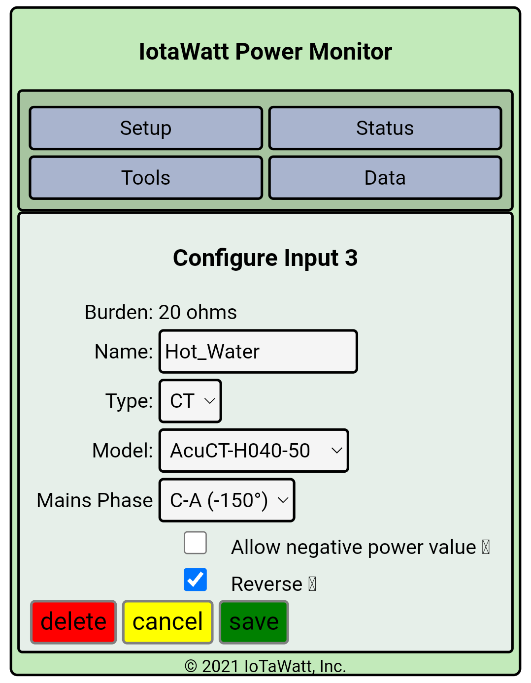
Two wire 208v load. CT is on the conductor connected to phase C and points towards the load and ‘Mains phase:’ is set to ‘C-A (-150°)’. Turns out that’s reversed, so the reverse setting is enabled.
(assumed that was the right orientation when I installed it based on the phase setting saying C-A and not A-C, gonna physically reverse it when my last order arrives).
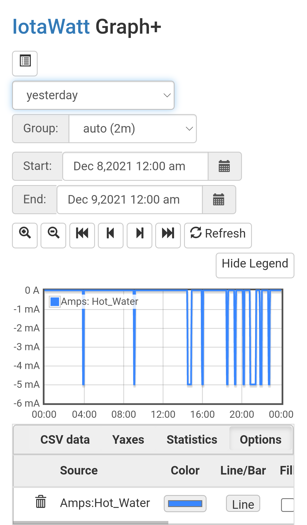
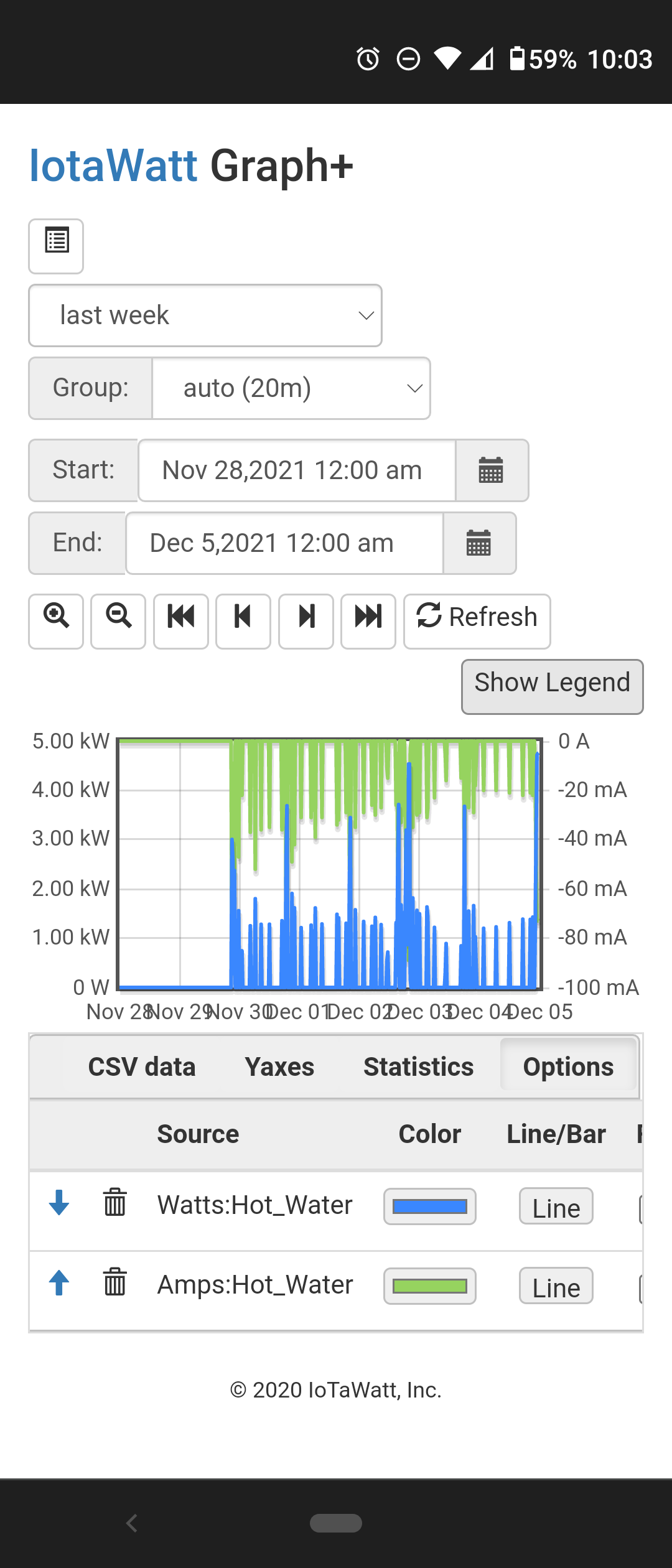
Graph+ displays this source as negative mA instead of the correct amperage. (I’m assuming direct input amperage before scaling and turning positive)
Amps graphed. (watts and all other metrics are correct)
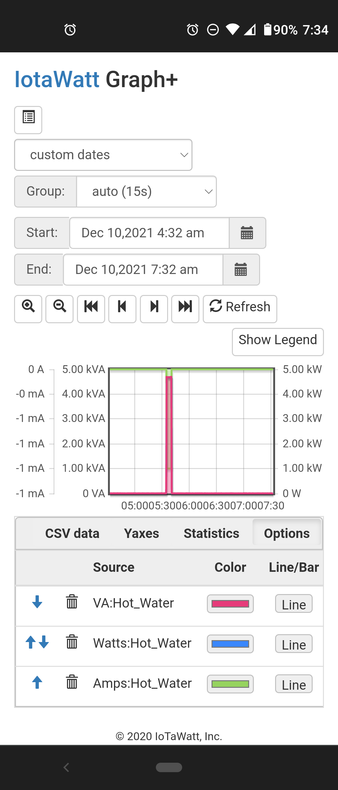
OK, the VA looks right. The IoTaWatt doesn’t save Amps directly, it saves VA and then divides that by V to get amps. So there is probably a problem with the script system and your 208V. That was all redone a few releases ago and it took awhile to discover a problem with Hz. So maybe there’s something else here. I’ll look into it over the next week or so.
I’ve uncovered the problem with amps. It effects any input with modified voltage. That would include any phase-phase reference in a three-phase system or any single-phase input that uses “double”. It will be fixed in the next release.
As in the Hz problem discovered last week, the data in the datalog is correct. It’s a problem with the scripting system.