DIY IoTaWatt V5.0

Hello from Germany.
With the info´s from Github i make my own IoTaWatt.
Here is some information that might also help others:

My own BOM (Maybe not entirely correct)
IoTaWatt V5 BOM.pdf (567.1 KB)

I ordered the PCB-board from JLCPCB with the Eagle Files from the IoTaWatt Github.
I ordered the parts from Digikey, Ebay and Reichelt.de.

I uses the free Software “DesignSpark Mechanical 4.0” for the housing.
I also printed the case with my 3D printer.

Greetings,
Michael

1 Like

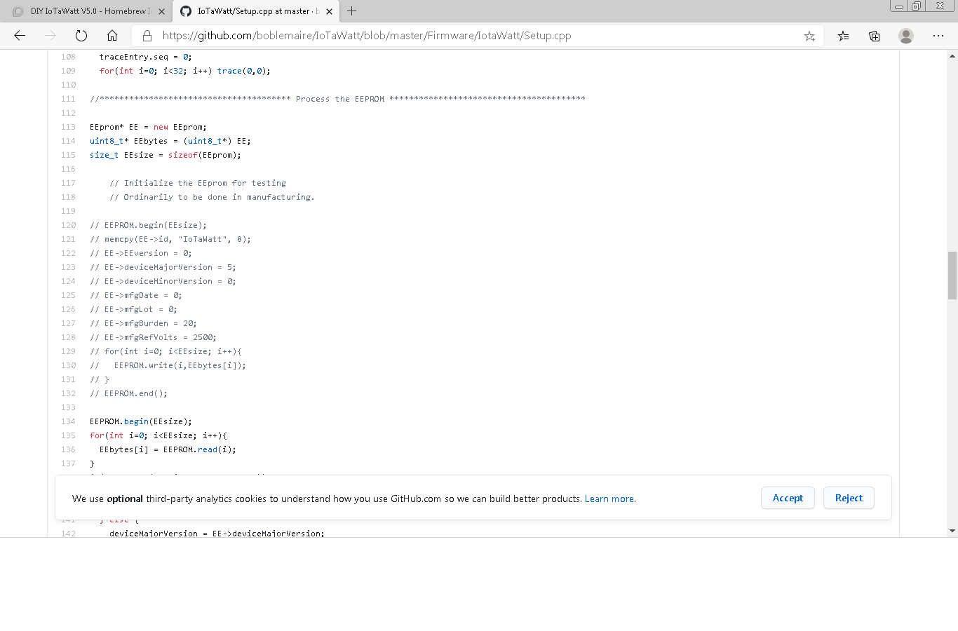
I build the Software from the IoTaWatt Github Firmware with PlatformIO and uploaded
to the NodeMCU.
I change the setup.cpp for the V5.0 Hardware for the EEprom.

And put the right files on the microSD Card (fat32).

Hey Michael

would it be possible to share the case?

Best
Sebastian

Hey Sebastian. Yes, it’s possible. I’ll try it on the weekend.

Thank you :slight_smile:

Sandblech do you think you find some time today or tomorrow? I’m still wondering that there is really nothing in Thingiverse.

Now you can find it!

Feel free to improve it. I use the Free Software DesignSpark Mechanical.

If anyone needs help with DesignSpark, you can hit me up and I’ll answer your questions.

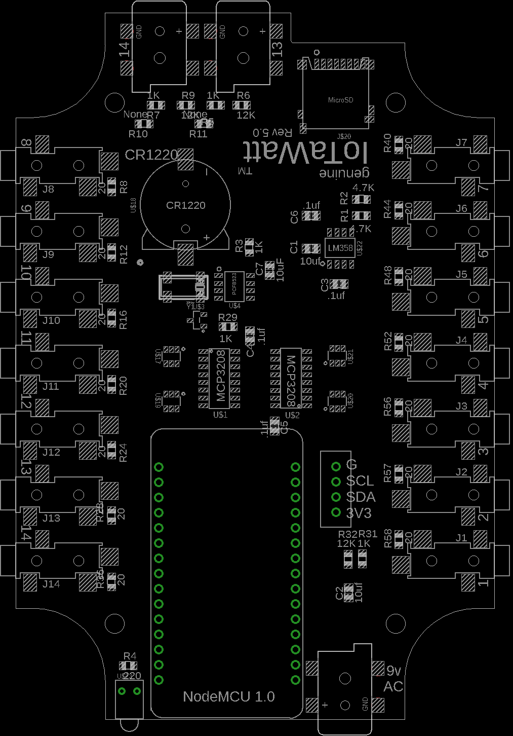
Can you provide a photo of your assembled pcb i am not able to get the connection of header 1x4 . In the iotawattv5.0 and i have 10358 ic instead of LM358 is it okay to use

The header is DNP in production boards and is there to allow adding an i2c chip such as an IO expander.

Hello,

is there an official BOM?

Thanks
Daniel

Also please specify about R10 and R11 register what are the values for three phase and without 3 phase

R10 and R11 are populated with a zero Ohm shunt if the board is built without connectors J16 and J15 respectively. Otherwise they are DNP.

I have connected the j15 and j16 but can’t find a zero ohm shunt can i just connect the terminals of resistors

And what if i just left them without any connection in my pcb can i work with the single phase j00 Vt jack

If you have J15 and J16, you should DNP (Do Not Populate) the R11 and R10 resistors. So you either populate J15 and J16 or you populate J11 and J10, but not both.

Okay thankyou i was worried about the assembly as i didn’t get a 0 ohm shunt and what if i didn’t connect them will i be able to run my iotawatt without connection at R10 and R11 thankyou for solving the doubt

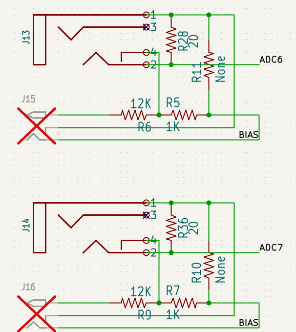
@Overeasy. For a single phase setup (i.e. not populating J15 and J16 and having 0 Ohms on R10 and R11. Would it make a difference if R5 and R7 are also populated with 0 Ohms and R6 and R9 are not populated (effectively making the circuits J13 and J14 circuits identical to all others) or does the firmware have compensation for the 1k series resistor between pins 1 and 4 on J13 and J14?

If you build it as designed, J13 and J14 will work like all the other current inputs as long as there is nothing plugged into J15 and J16. The switches in the jacks determine which input is in use. That said, if you just don’t want to populate J15 and J16, you can put a zero Ohm resistors in R10 and R11, effectively doing the same job as the switches in J15 and J16. In that scenario, the 12K and 1K resistors are not functional and can be populated or not.

1 Like

Is it still appropriate to use IotaWatt5.0.brd?
GitHub shows it’s 6 years old, so the current version has likely diverged significantly.