I did just open another post but wanted to keep the two separate for easier conversations.
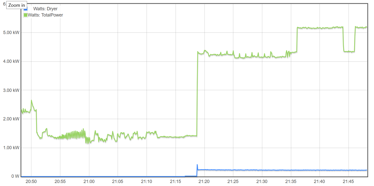
I recently installed a 100A current clamp on my dryer circuit but I’m getting readings that are ~10x too low. I attached an image showing the total power measured, which seems right, and the power on that circuit. I believe I have that clamp attached correctly for the dryer by having the two wires going through in opposite directions. I tried reseating it but that didn’t seem to help.
Are you sure the two conductors are going in opposite directions? That looks like the drum motor, which is usually 120V and what I would expect to see if the two conductors were cancelling out the 240V heater. Try running the dryer on tumble only and see if you get the same thing. Can you post a picture of the CT as installed?
I’ll try to get the panel open this week to double check. I created a loop in order to get current flowing the correct way, but now I’m wondering if I ended grabbing the wrong part of the loop.
Seeing some power is what threw me off. Didn’t occur to me that parts of the dryer would be running off 120v only. I assumed I would see nothing if I installed the CT wrong.
Sorry it took me awhile, I had a few other projects up before I could take the panel cover off.
It wasn’t on correctly. I made a little loopback to allow measurement but grabbed wrong part of the loop.
Might be worth mentioning on circuits like a dryer that it is possible see some power due to a device being 120v.