Going over this setup, I think its necessary to check “allow negative power” for the three mains while doing this experiment.
If that was not checked, note when they are changed so that we can disregard data from before then if need be.
Going over this setup, I think its necessary to check “allow negative power” for the three mains while doing this experiment.
If that was not checked, note when they are changed so that we can disregard data from before then if need be.
ok thanks. I will change now and keep it over night
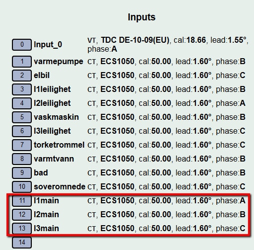
Could you also assign:
Main1 phase A
Main2 phase B
Main3 phase C
Thanks
OK. updated config. thanks
Hi again,
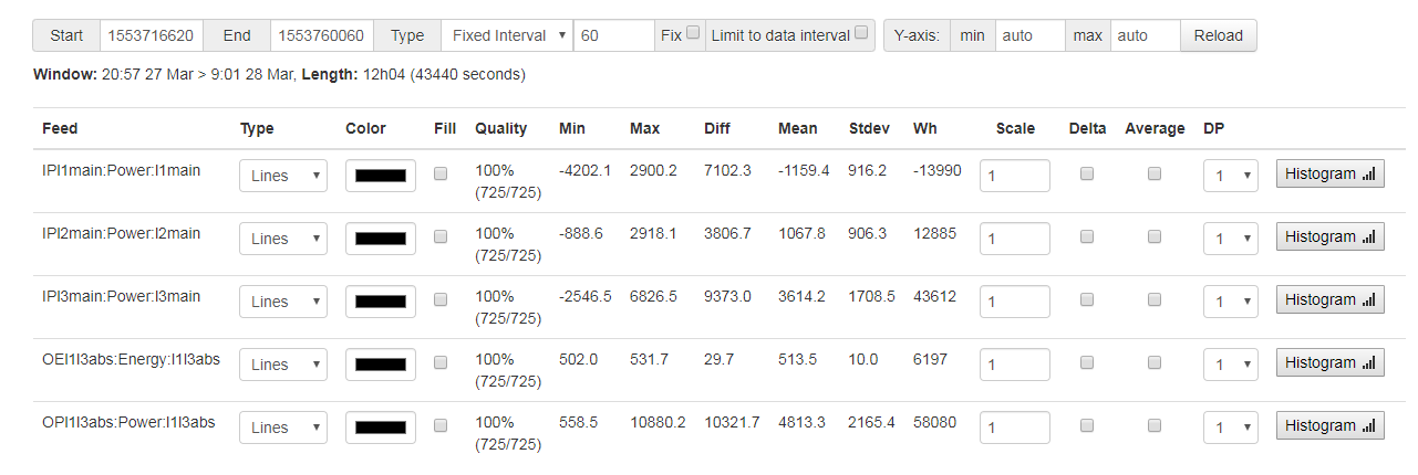
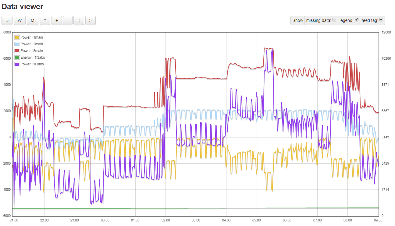
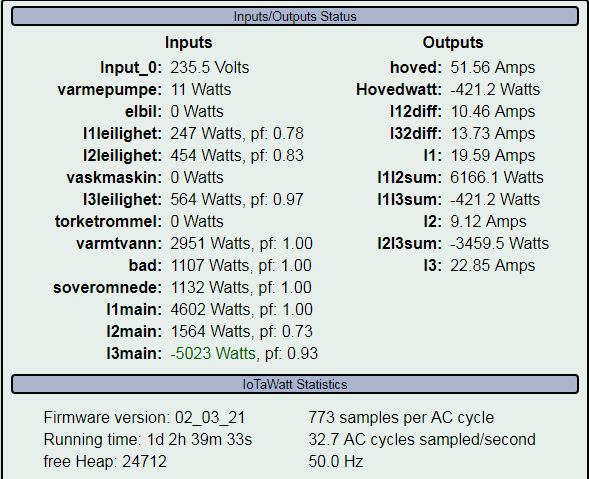
So after 12 hours with following settings:
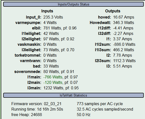
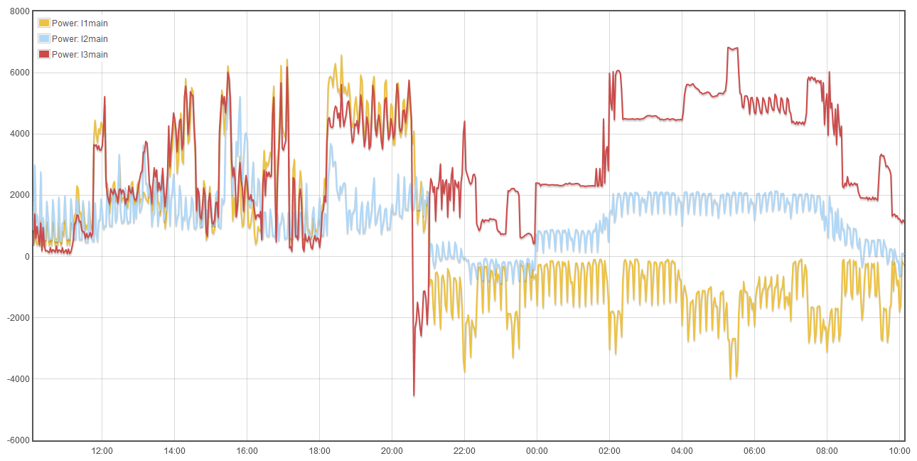
Power looks like this:
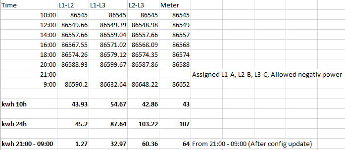
Not sure how relevant at this stage but comparing kwh output from iotawatt vs meter last 24h and 12h it looks like:
CI had my money on L1-L3 with the new settings, but now I’m looking at how accurate the L2-L3 is before the change. Just to be sure I have that right, before the change main2 was phase A, and main3 was phase B, is that correct?
Being more of a programmer than electrical engineer, we may have to stumble on the solution here, but I would like to understand the ultimate solution, and be able to produce a methodology for others to do this.
I’m assuming that you are getting the most recent data directly from the IoTaWatt, rather than using the influx integral function. I have had anecdotal reports of that not working quite right with negative numbers, and I believe that this measurement method can produce them. There will be a solution to that potential problem once the proper setup is identified.
In the meantime, I’m still scratching my head. Can you verify that the VT is connected between L1 and L2?
UPDATE; @Giraffe, are you following this? I’d be interested in your input.
Hi,
Settings before last test was:
Main1 - B
Main2 - A
Main3 - B
VT is connected to L1-L2.
Data compared with my meter is based on summed values from kwh output from iotawatt to influxdb.
Very much appreciated help so far. I could most likely live with the previous setup, as all my individual circuits seems to be working fine (1kw - electric heating = 1 kw on the iotawatt, 3kw on the warmwater = 3kw on the iotawatt, etc), but would be happy to conduct more tests / configurations if this would be interesting.
One interesting observation that might help with confirming VT location / orientation is:
When L1, L2, L3 is set to A
L2 shows positive watts, L1 and L3 negative
When L1, L2, L3 is set to B
L3 shows negative watts, L1 and L2 positive
When L1, L2, L3 is set to C
L3 shows positive watts, L1 and L2 negative.
Sum of watts on above 3 combinations is always 0.
Might be a longshot, but found it as an interesting observation.
I agree that the previous setup seemed to give the right solution. I’d like to take a look at one more thing:
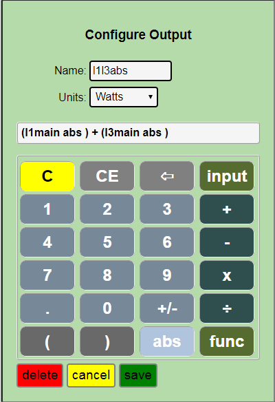
I’d like to retrospectively look at that data from 21:00 - 09:00. I’m curious if the allow negative values is the reason the L1L3 doesn’t work as I had expected. We can test this by defining an output as:
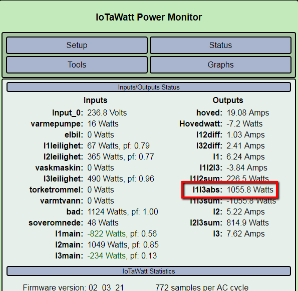
(I1main abs) + (I3main abs)
Then take a look at the sum of those values over the 21:00 - 09:00 period. I think it will be 64.
Something is off there, the result still goes negative. Could you show the output definition in the setup output display?
Thanks, I see the right axis now. I now realize that this can’t be done retrospectively. The algebraic sum of each main is converted to absolute value, which is not the same as converting each individual measurement to absolute value. So this doesn’t work. Sorry. it would have to be done by removing the allow negative values and running for awhile.
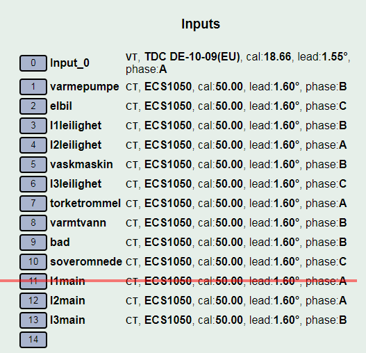
This is how I understand it to be setup:
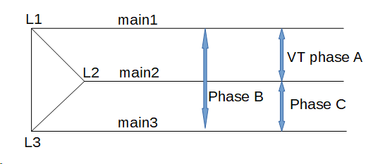
So in the earlier period when L2+L3 were correct, L2 was assigned to phase A and L3 was assigned to phase B, which resulted in both referencing L1 for voltage, as the method describes. You only need two mains CTs, so any of these should work when added together (allow negative values off):
main1 phase A
main3 phase C
main2 phase A
main3 phase B
main1 phase B
main2 phase C
The individual circuits are basically single phase, so they should be:
L1-L2 phase A
L2-L3 phase C
L3-L1 phase B
If you could double check that this is how you have it and it works, that would be great. I wanted to lay it out for the next person that needs to do a three-wire system. Please get back and confirm the accuracy of the results.
If you choose the first mains option above, main1, phase A and main3, phase C, with the extra input from removing main2 you could connect CTs to L1-A and L3-C on that branch meter and the sum should match that meter.
Excellent ! I will "re"configure my iotawatt and revert with results tomorrow. Again thx for all the support!
Hi,
So after ~10 hours it looks like we are spot on kwh usage between iotawatt and my meter !
From 23:00 - 9:00 I have used 38kwh both on the iotawatt and the utility meter.
I used the following setting where I am using sum of kwh from L2-L3.
Just following up to be sure this is working correctly. Does your energy meter agree with the IoTaWatt now?
Spot on ! Everything works perfectly !
Hi all,
this topic has been very useful for me, as I have a grid connection “3-phase 3x230V (3 phase wires, no neutral)” (still quite common in Belgium, next to the 3x400V+N connection type).
However, @overeasy , I don’t understand why we wouldn’t allow negative values.
Because in case of a load with power factor between 0 and 0.5, it’s possible that one of the two measured values becomes negative. (cfr the “two watt meter method”)
Could you clarify your reasoning?
Thanks a lot.
Hello Michael,
It took me a few minutes to go back over that thread from a year ago. As you can see, that was my first exposure to this kind of system. In the interest of full disclosure, I am a programmer by trade, and have no formal training in electric power systems. Most of what I profess to know I learned through the miracle of the internet over the past few years on this project. That said, it’s not rocket science, at least not as applied for energy monitoring. So at the risk of embarking on another learning experience (which would be fine), I’ll tell you where I’m coming from on this.
To directly address the “allow negative values” question, I don’t believe it matters if there is no exported power from an alternative energy source. That is to say that when consuming, I believe the power should be positive on both legs at all times. I could be wrong about that in some extreme case, and if so, I’m pretty sure checking the “allow negative power” would resolve it.
Could you explain why you think a low power factor would cause negative power?
Fundamental to this question is the notion of what the power measurements on each of the two meters (CTs) really represents. With this two meter method, the sum of the two is the total power delivered through three conductors.
Although this two meter method produces an accurate power measurement, it does not accurately address power factor. A third CT would be needed to determine total VA, and the then the total power factor could be determined as P(total)/VA(total). I don’t know of any way to express a correct power factor for the individual legs.
I use this article as a pretty good reference for how it all works, and it also explains why you need to add a third meter to get accurate power-factor.
I’ll come back with a thorough explanation. Need some time to figure it out and document it in a clear way. At this moment, time is missing ;-). I’ll put it on my to do list.