New Australian Install - 3 Phase/solar/battery with second single phase solar array

Hi all
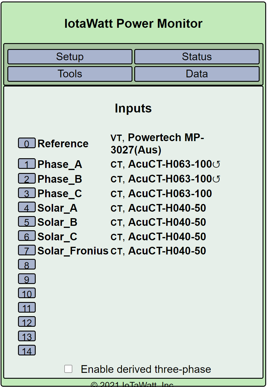
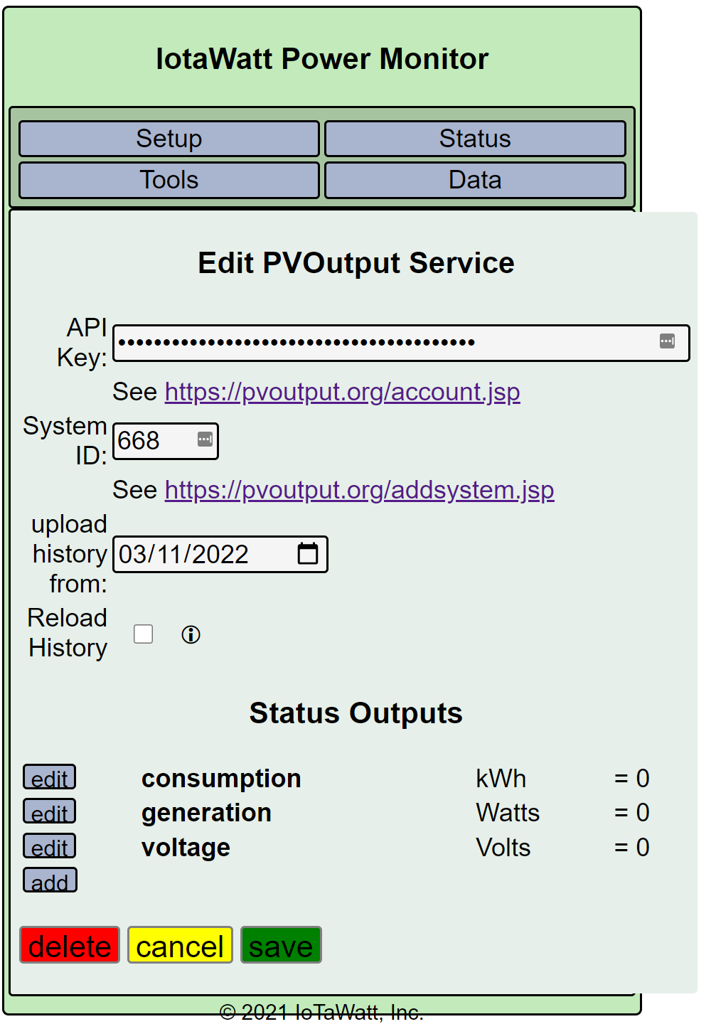
I’m currently building my forever home and decided on Iotawatt for my energy monitoring. I’ve used various monitoring platforms over the years including currentcost, smappee, efergy, SMA Home Manager etc but have never really been happy with any of the solutions from an accuracy perspective with the exception of the SMA Home Manager. The drawback with that is that I have been on PVOutput for about ten years and exporting the solar data required third party programs that often broke plus I either had to punch in my consumption data from my smart meter manually or use a seperate consumption monitoring platform such as Smappee. Looking for something better, I found Iotawatt and have just received my bundle this week. I ordered the Aussie bundle with 3 x 100a CT clamps and 11 x 50a CT clamps.

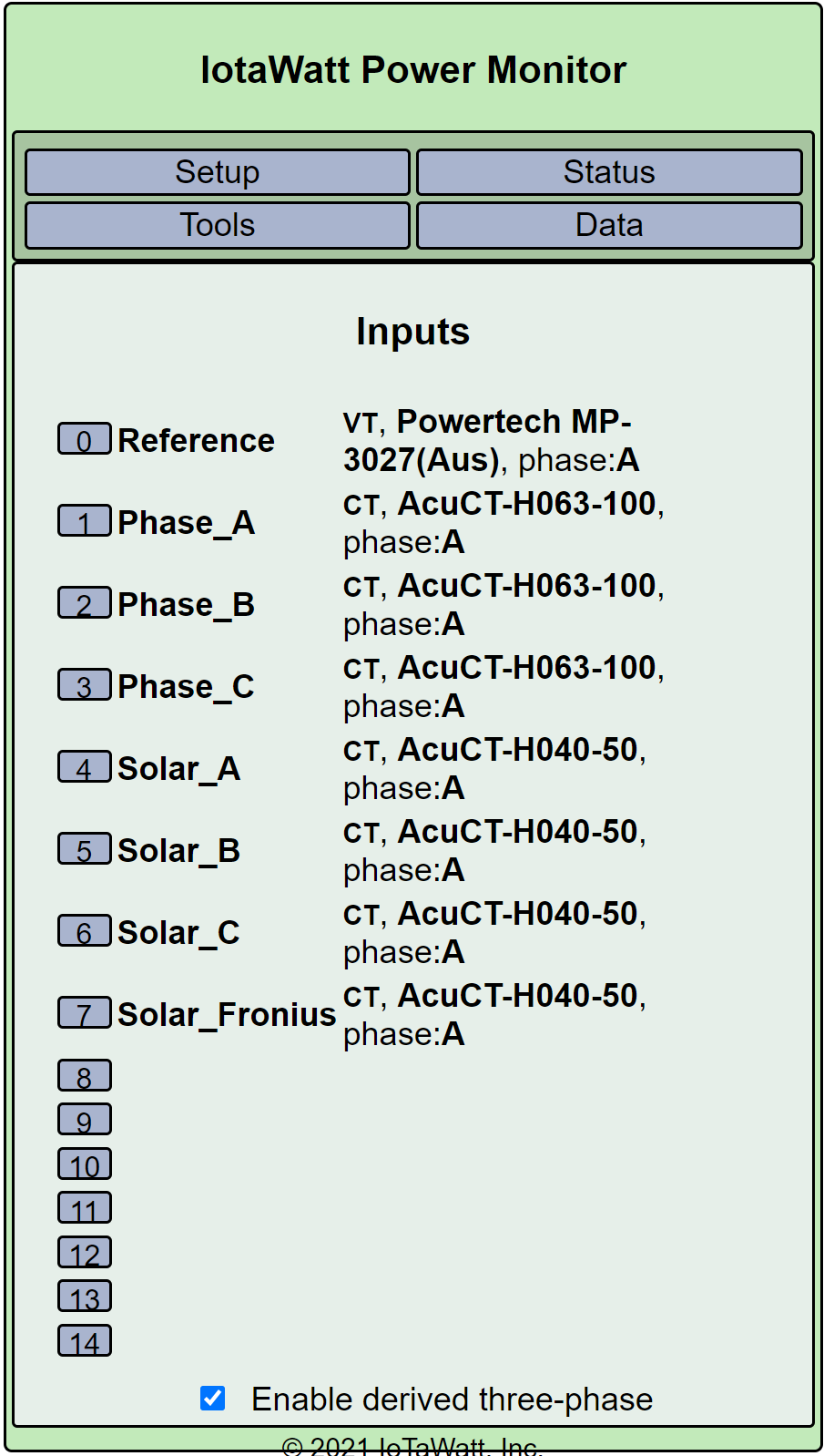
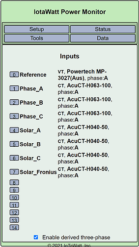
My current setup in my new home will be 3 phase power with an SMA Tripower Solar Inverter (3 phase) and 13kW of panels. I have 3 phase ducted aircon. HWS is a Sanden Heatpump.

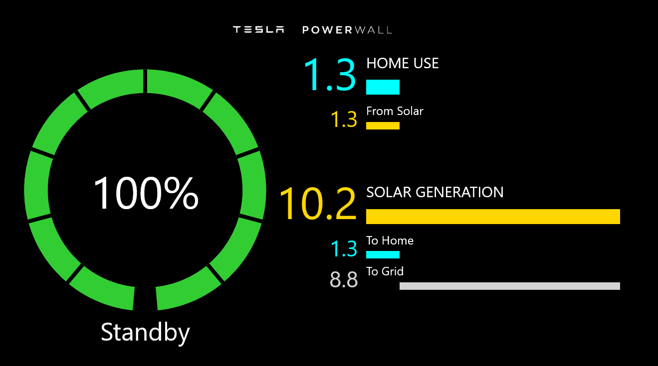
I am considering adding a battery (Powerwall 2) and/or a second inverter and extra panels which would not be feeding back to the grid due to retailer limitations. My Distributor (Endeavour Energy) allows up to 10kW of PV generation per phase i.e. 30kW maximum. We may go down the EV route in the future, but that is not in the current plans.

Talking to my solar installer, they are recommending that if I add additional solar to use a single phase inverter. If I add a PW2, it is single phase but there is some way that it gets wired up to supply all three phases apparently. However, during a blackout, it will only supply one phase. If I add the PW2 and solar, it is set up as a virtual circuit. I haven’t received the detailed proposal as yet so I’m not sure of the exact way this would be set up.

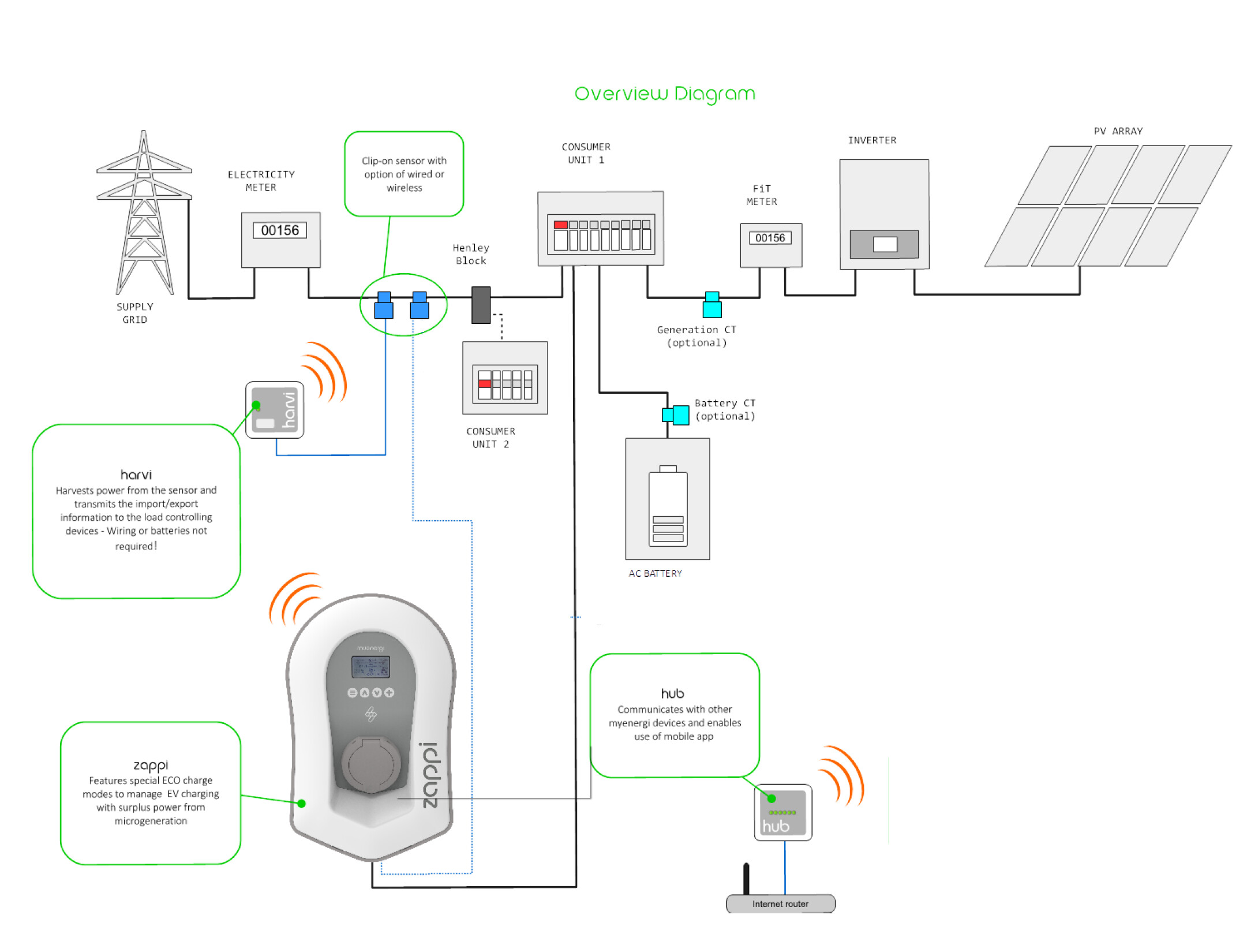
So I’m after some advice about how best to connect the Iotawatt (and whether I need a second unit). My installation scenarios are:

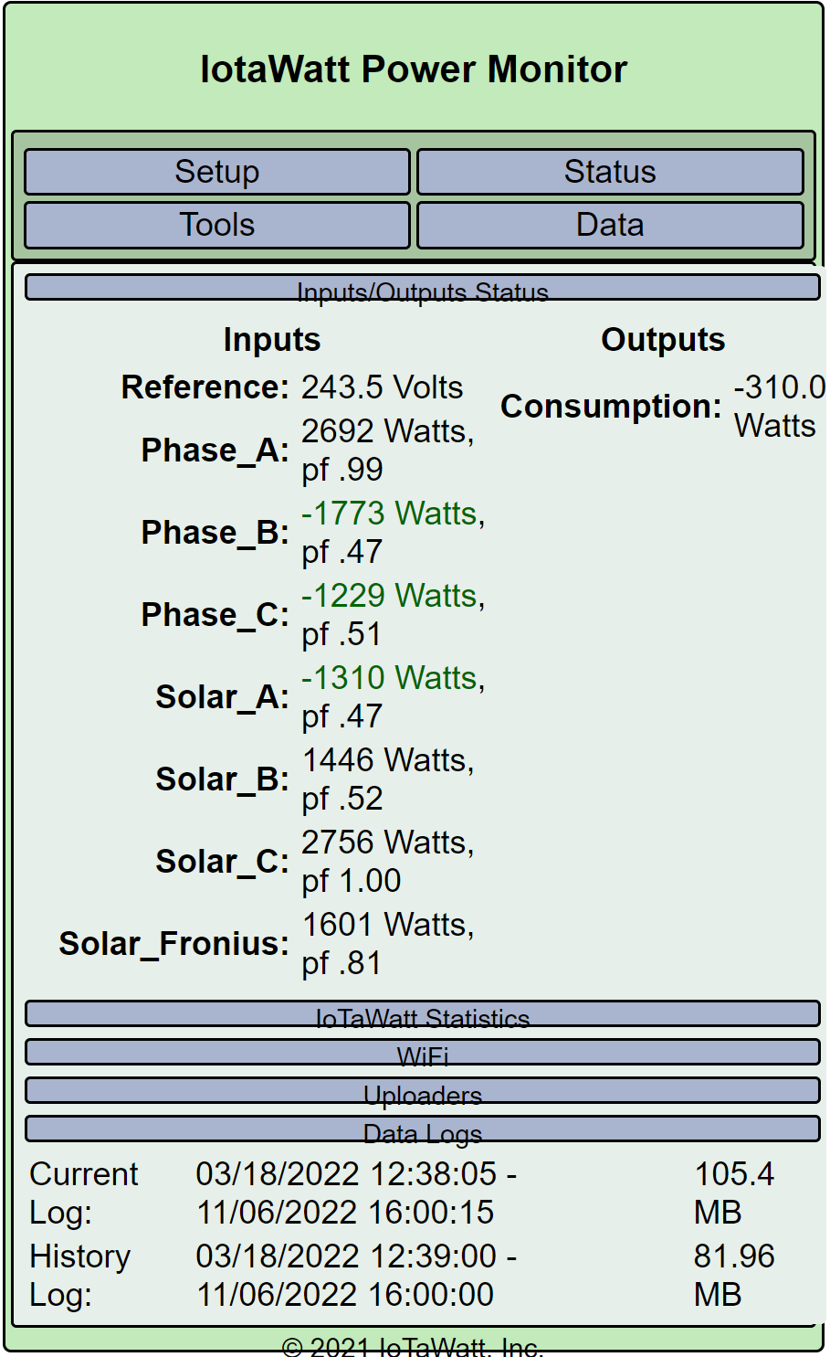
  1. Existing - 3 Phase power with 3 phase solar Inverter and 3 phase aircon.

  2. Option 1 As above but add additional single phase solar inverter and panels - no battery

  3. Option 2 Existing system and add Powerwall 2 with no additional solar

  4. Option 3 Go the whole hog and add the extra solar and a battery

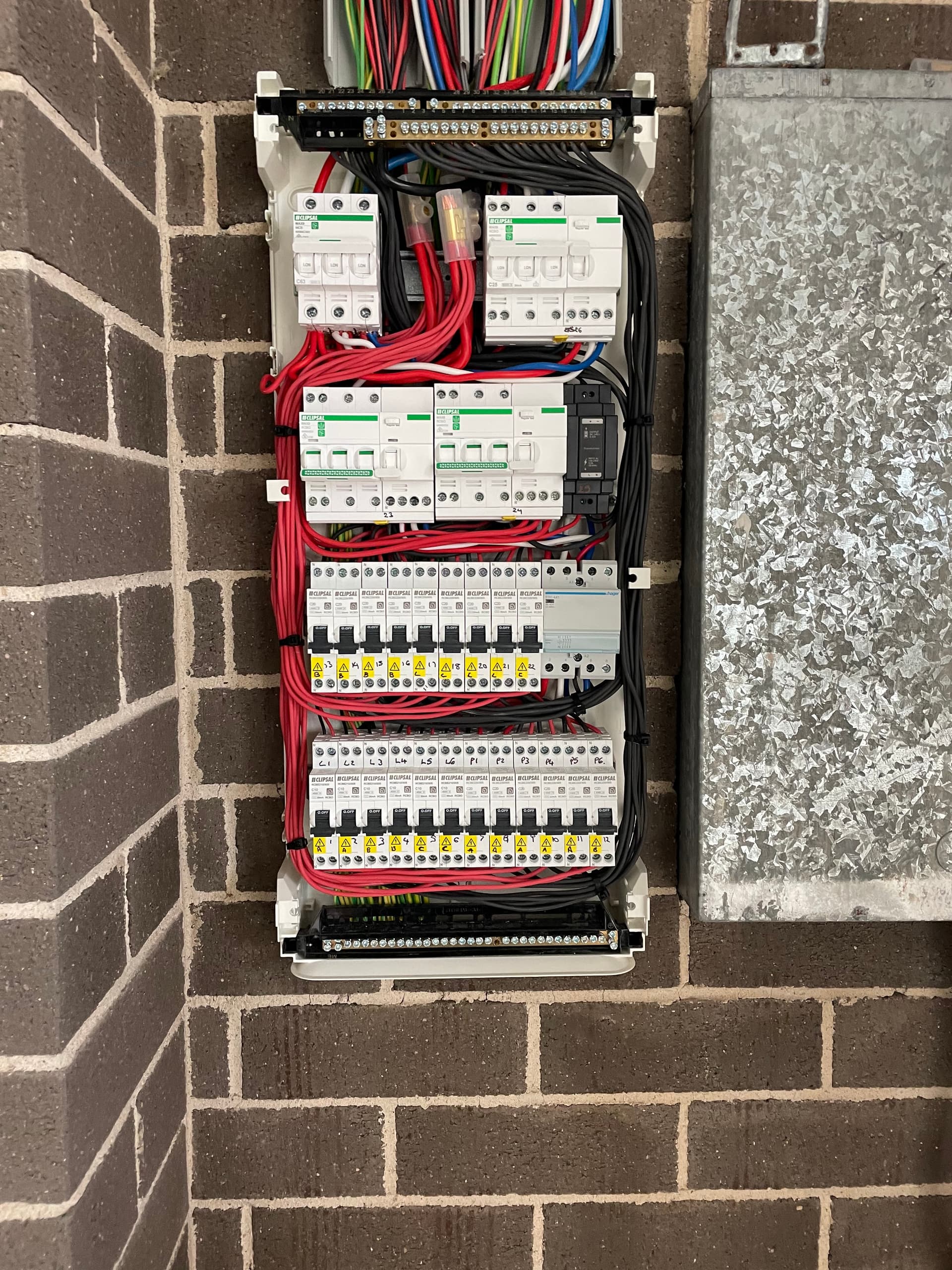
In terms of circuits, I’m not sure whether I need to include any controlled loads or not. I’ve never had them in my previous setup. At this stage, I am not planning on it.

I’ve got a bit of time as my house won’t be finished until May. However, the existing solar gets reinstalled in a couple of weeks and if I add the battery and/or extra solar I will do it then.

My questions are

In my existing system, I understand that I need 1 x Iotawatt with 3 x 100a clamps for the 3 phases and 50a clamps for the various circuits

If I upgrade to any of the other options, is the wiring up of the Iotawatt still the same or is there anything that changes? If I have any controlled loads does anything change?

If I add a powerwall and additional solar, is 1 x Iotawatt sufficient (assuming I have 11 circuits or less in total, plus the 3 phases)

Thanks in advance

This is what gives me pause. To offer any advice at all, would need a line drawing of the various configurations and some indication of what you want to measure in addition to grid import/export, solar production and usage.

With the PW, there is more going on, and I don’t know anything about a single-phase to three-phase capability.

My understanding is the PW2 gateway (inverter) monitors all 3 phases but the PW2 battery is only single phase. The gateway totals the amount of electricity being imported and exports the same amount to the grid, effectively zeroing out the import. e.g. If I am using 6kWh across 3 phases, and my solar is producing 3 kWh, I am importing 3kWh from the grid. (1 kWh per phase) However, the gateway will simultaneously export 3kWh on one phase, giving a net import of 0kWh from the grid. I found this diagram that might make more sense. Currently I have a 3 phase solar inverter and have the option of adding either a single phase or three phase inverter if I add more solar. The only real difference is if I want blackout protection, I need to add a single phase inverter. However, from a load balancing perspective, another 3 phase inverter makes sense. BTW, the PW2 and gateway are AC coupled, not DC.

Ok, to monitor that setup I would put a CT on each of the three incoming mains, one on the solar inverter output, and one on the PW2 feed.

Thanks Overeasy. I’m going to hold off with the battery for now but add extra solar and a second inverter. My primary PV System is 13 kW of panels on a three phase SMA 10kW inverter. The additional solar will be 6kW of panels on a single phase Fronius Symo Inverter. Assuming the single phase solar is on phase 1, does this alter your advice? The diagram I posted earlier doesn’t show the 3 phase inverter.

Hi all

Since my last post, I installed a second 5kW single phase PV inverter and an extra 6 kW of panels which will be feeding back to the grid as a found a plan to accomodate that. I also ended up ordering a Tesla PW2 and my wife bought an EV, so my installation will now include a 3 phase 22kW EV charger (Myenergi Zappi V2). The house is around 6 weeks away from completion. The system I am planning to monitor now will look like this:

PV System 1 - 3 phase 10kW PV Inverter -
PV System 2 - Single Phase 5 kW PV Inverter
Battery - Tesla PW2 and Gateway 2
EV charger - Zappi v2 22kW 3 Phase

Plus all the other circuits including:
Aircon - 3 phase
Hot Water - Single phase
Pool pump (to be installed - not sure if single or 3 phase)
Oven 1
Oven 2
Induction Cooktop
Not sure about the rest of the circuits at this stage, but the electrician said he will need to install a sub board to accommodate all the circuits, so I’m pretty sure I will be over the 14 available on a single Iotawatt, meaning I will probably have to get a second Iotawatt if I want to monitor everything. My question is for the Zappi (or any other three phase device) I’m assuming a I just need to clamp the 6mm 4 wire cable (3 cores plus earth) supplying the Zappi with a single CT clamp for the Iotawatt to monitor consumption on that device. Is that correct?

My other question is about CT clamps. The Zappi EV charger and the Powerwall 2 both use CT clamps as well, so I would have 3 x CT clamps on each phase (if they all fit) one for the Iotawatt, one for the Zappi and one for the Powerwall. Assuming there is room to mount all three clamps on each phase, will this cause any interference between the clamps?

From my research, while the Myenergi App and the Tesla app provide very pretty and detailed energy monitoring themselves, they are not as accurate as the Iotawatt, being between 5% to 15% out compared to the billing meter from some of the reviews I have read. While I don’t really intend to rely on either the PW2 or Zappi for my energy monitoring (The Iotawatt being the reference device or source of truth and reporting to PV Output) I still need to install the respective clamps to enable the functionality of the devices. The diagram below shows where the Zappi clamps need to go. The diagram shows a single phase installation and differs from my meter setup in that I have a smart meter, which will calculate import and export to the grid, so there is no seperate FIT meter between the PV Inverter and switchboard as shown. The diagram also shows their single phase inverter so there are actually 3 x CT clamps between the Zappi and the meter instead of the single clamp shown.

Negative. You would need a CT on each of the three “cores”.

They can interfere with each other if the iron cores are touching. I’d recommend trying to keep at least 1/4 inch between the CT bodies.

Thanks again for the advice.

Am I on the right track?

Looks plausible. Don’t know about the powerwall.

Hey can i just say - if you have an IOTAWATT (yes you will need a 2nd one for the sub board) - you should seriously look at the OpenEVSE charger as it has a lot more flexibility in terms of how you want to apportion your charging and excess solar etc.

For instance you might have 10KW being generated and the house using 5KW of that - now depending on where you place the CT clamps for the Zappi and the Powerwall one will take precedence over the other i.e. the powerwall could suck up all the excess PV if its clamps were first and the Zappi would nto see any excess going to the grid so it would not start charging until the Powerwall had finished.

On the other hand if you put the clamps the other way around then the Zappi may steal all the excess and direct it to the car and until it is full not be able to charge the PW.

If you go down the path of the OpenEVSE you can programatically tell it to charge at X value - so you could tell it to only send 2KW to the car and leave the other 3KW to the PW (or any other combination)

Where this comes in handy is if you know you are not going out today so do not need the car fully charged until tomorrow but do want to peak shave from the grid from the powerwall.

Conversely - you might know you are going to be out all afternoon with the car so you could prioritize all charging to the car first

This can all be done easly with a Raspberry Pi and a visual programming language Node Red

Craig

Thanks Craig

It looks like I will be using a Wallbox EVSE as it is being supplied and installed by Genesis with the GV60 I ordered, so I won’t be getting the Zappi after all. Not sure at this stage if they are supplying the single phase version only or three phase version for three phase properties. Sub board has been installed this week, but the solar and PW2 can’t be done until after handover, which is a few weeks away. Looks like it will be pretty tight for attaching clamps, when the cover is on.

Man that is horrible what they have done to you there - they should have run a proper subboard with Buzzbars and given room to work in the future.

I have an industrial sub board for my setup and it is so much easier to move around in there with all the RCBOs attached to central rails (3 phase)

Craig

The builder would be paying them the minimum they can, so they would have been working within their budget. Not much I can do about it until I get possession, and then I’ve got to decide if it is worth the cost to change to a bigger sub-board. My neighbour is a sparky, I’ll get his view once we move back.

Finally got the EV charger and powerwall 2 installed so I could start setting up the Iotawatt. I have it connected to the 3 phase power and both inverters only at this stage, but I suspect some of the phases are reversed, even though they are all clamped in the same direction.


The solar is currently producing 14kWh between the two inverters but this is what I am seeing on the IotaWatt:

My other issue is that although I have set it up to upload to PVOutput, and it appears to be working correctly, no data is being uploaded to PVOutput.

SD initialized.
11/05/22 23:38:06z Real Time Clock is running. Unix time 1667691486
11/05/22 23:38:06z Reset reason: Software/System restart
11/05/22 23:38:06z Trace: 1:3, 1:3, 1:3, 1:3, 1:3, 1:3, 1:3, 1:3, 1:3, 1:3, 1:3, 1:3, 1:3, 1:3, 1:3, 1:3, 1:3, 1:1[4], 1:2[5], 9:0[5], 9:0, 9:1, 8:4, 8:6, 8:8, 8:9, 9:2, 1:2, 1:3, 1:3, 1:3, 10:13
11/05/22 23:38:06z ESP8266 ID: 429842, RTC M41T81 (68)
11/05/22 23:38:06z IoTaWatt 5.0, Firmware version 02_07_05
11/05/22 23:38:06z SPIFFS mounted.
11/06/22 10:38:06 Local time zone: +10:00, using DST/BST when in effect.
11/06/22 10:38:06 device name: IotaWatt
11/06/22 10:38:06 HTTP server started
11/06/22 10:38:06 timeSync: service started.
11/06/22 10:38:06 statService: started.
11/06/22 10:38:06 dataLog: service started.
11/06/22 10:38:06 dataLog: Last log entry 11/06/22 10:38:00
11/06/22 10:38:10 WiFi connected. SSID=Perseus24, IP=192.168.1.208, channel=6, RSSI -69db
11/06/22 10:38:10 MDNS responder started for hostname IotaWatt
11/06/22 10:38:10 LLMNR responder started for hostname IotaWatt
11/06/22 10:38:10 Updater: service started. Auto-update class is MINOR
11/06/22 10:38:11 historyLog: service started.
11/06/22 10:38:11 historyLog: Last log entry 11/06/22 10:38:00
11/06/22 10:38:11 Updater: Auto-update is current for class MINOR.
11/06/22 10:38:16 PVoutput: started
11/06/22 10:38:16 PVoutput: System The $un God, interval 5, donator mode
11/06/22 10:38:17 PVoutput: Start status beginning 11/06/22 10:40:00

Follow the docs for three-phase mains setup. You must enable derived reference and determine phase assignment. If you have the three mains CTs oriented the same way, then you should not have reverse checked for two of them. You would either reverse all or none, depending on the polarity of the VT.

Hi Bob

Did that. Tested the phases with a kettle and swapped the inputs to match the phases as per the guide. All the clamps are clamped in the direction of the flow This is what it looks like now.

The Powerwall is reporting similar figures to what I’m seeing on PVOutput from the inverters, so it looks like I still haven’t got it right, as it is quite different to the IotaWatt.
.

I’m also still seeing nothing on PVOutput

It does not appear you completed the setup https://docs.iotawatt.com/en/master/threePhase.html#identify-the-other-two-phases

I recommend you do this at night when the solar is not producing. Afterward, you will need to set the solar inputs to their corresponding phase reference as well by identifying the associated mains.

You are uploading zeroes. What do you expect? If you intend to have the inverters continue to upload to PVoutput, as opposed to uploading the combined solar production via IoTaWatt (when you get it setup properly), then you should remove the generation output from the IoTaWatt PVoutput setup.

There is no context to this Powerwall display shown. What is the time period? Is that Watts or kWh?

I did, by plugging a kettle in to phase A and B as per the guide. I didn’t do phase C because I figured that was self evident if A & B were correctly identified. But, will do again today to make sure it is done correctly.

Should the inverters be showing positive or negative readings?

I’m expecting to see consumption as a separate figure to generation with the blended figure being the net amount. At least, that’s how it worked when I used to use a Smappee or Efergy to monitor consumption.

I’m only using the inverter uploads until I get Iotawatt working properly. That said, I have 3 systems on PVOutput which are aggregated, The original system is the parent, system 2 uploads the Fronius data and system 3 uoloads the SMA data. I had set up Iotawatt to point to the parent system and upload to there so theoretically, the inverter uploads shouldn’t affect it, except that it would be doubling up on the generation data as it would be receiving the inverter data plus the generation data from Iotawatt. I would rather have just kept to one system but PVOutput doesn’t let me add to the system and keep my historical data, so I had to set it up as an aggregated system with parent and child systems. For the moment, I have set up a test system on PVOutput which I have pointed IotaWatt to until I have it uploading reliably.

That was a snapshot of the powerwall at the same time as the snapshot above it from Iotawatt. Figures are in kWh so when the Iotawatt was showing -310w consumption, Powerwall was showing 1.3kWh consumption.

These are all assigned to phase A: