I think connected to the correct phases now.
Your phase assignment for L2 and L3 are incorrect. Try swapping them.
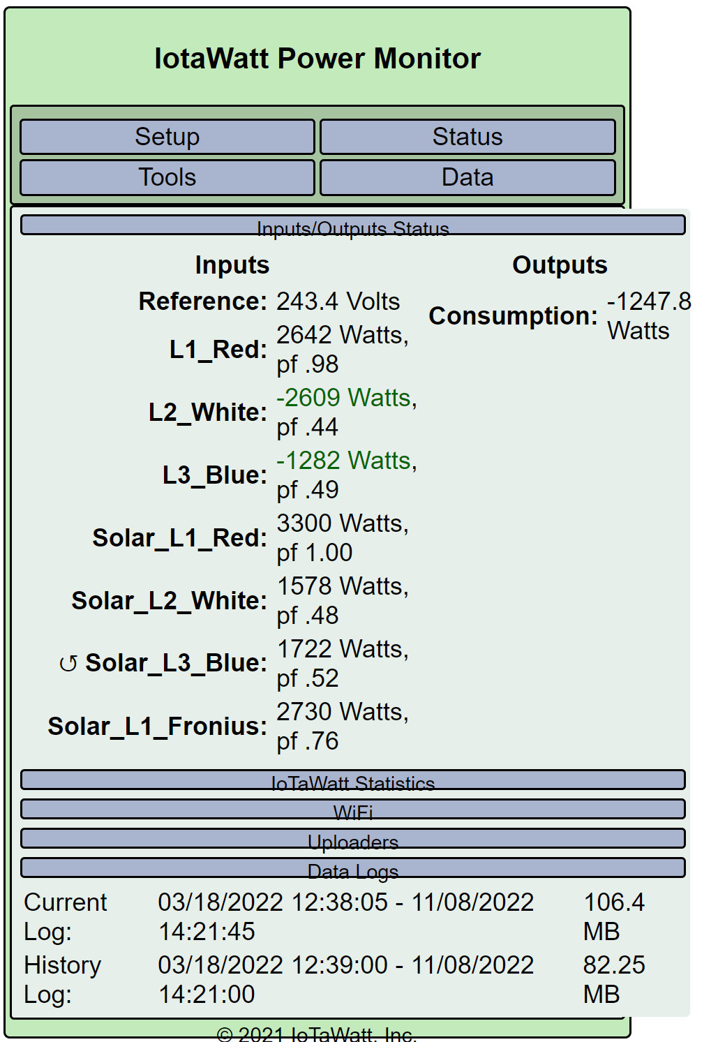
Hi Bob. Swapped them around as per your suggestion:

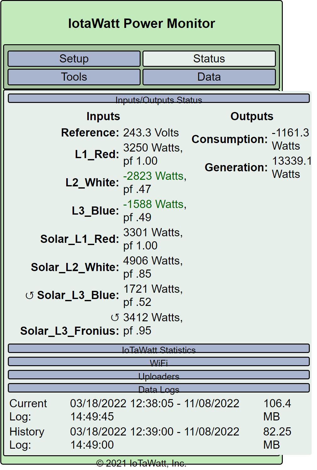
However, my consumption data is now way off:
If I leave the L2 and L3 as is and change Solar L2 to B-C, I get within 500W of what the inverters are reporting:
If you want to just keep trying random things and guessing if it’s right, have at it. It’s definitely wrong.
Hey Bob, don’t get shirty, I appreciate the help. I know nothing about how to configure this properly and the whole point of getting an IotaWatt was to get accurate figures, so I’m in your hands. I’ve put the solar phase assignments back to what they were.
Going back to your suggestion earlier to swap the phase assignment for L2 & L3, I did that but the consumption is way over what it should be. I’d be expecting a consumption figure of around 1000w - 1500w or thereabouts but swapping the phase assignment gives a much higher consumption figure. Is that right?
I don’t even know if your consumption formula is correct, and you have multiple obvious problems with your setup. Clearly you have not performed the derived three-phase setup procedure, or you would know this. Moreover, working on this while the solar is producing makes it much more complicated.
I generally try to fix one thing at a time and move on, starting with getting the mains right and agreeing with your meter, then moving on to the inverters etc. If you expect there is one magic thing that will make everything suddenly work, that would be following the setup guide to the letter.
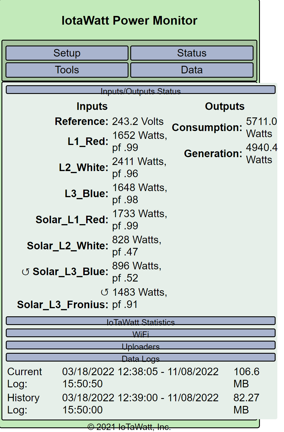
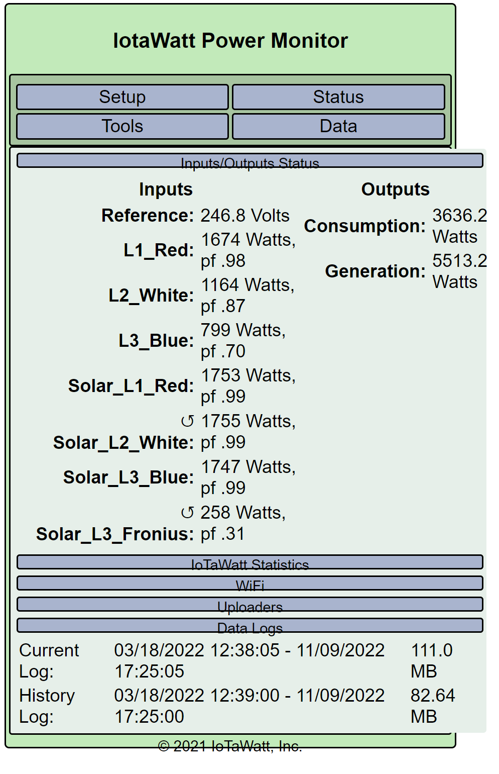
All that said, you seem to think that the above result with the mains phases swapped is wrong. Let’s look at that. You are showing a total of 5,711 Watts flowing through the mains. I am guessing that you don’t have “allow negative values” checked on the three main inputs and if you did, that would be -5,711 Watts. In other words, I think you are exporting 5,711 Watts.
Looking at your solar, you apparently didn’t swap the phase assignments for the Solar_L2 and Solar_L3. Going by the L2 and L3 commonality, they should probably be Phase C and B respectively. This is also indicated by the low power factors of the those inputs.
The Solar_L1_Red indicates 1,733 Watts. Let’s assume the three-phase inverter outputs similar power on all three-phases. That would be 5,199 Watts from the three-phase inverter.
I don’t know if the Fronius inverter is actually on L3 (phase B). The last post shows it on L2 (Phase C). That may be correct, as the power factor is high. If we go with the indicated 1,483 Watts, the total Solar would be 5,199 + 1,483 Watts = 6,682 Watts.
By mu calculation, if you are producing 6,682 Watts and exporting 5,711 Watts, your consumption would be 971 Watts.
I think that passes the reasonability test, although I would want to validate the mains using the meter and get some agreement of the solar using the inverter stats.
I don’t know if you have the Powerwall online, or how it fits into the picture. Suffice to say that batteries are a more complex problem and probably will require more CTs to understand what they are doing.
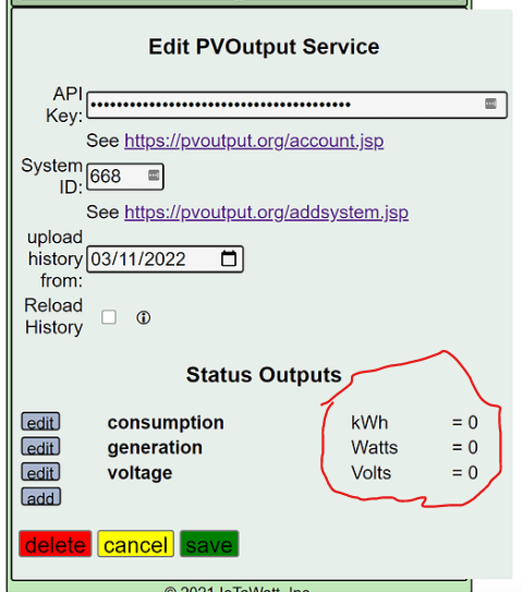
When I say you are uploading zeroes to PVoutput, I mean you are uploading zeroes:
Agree
I’ve followed your guide for setting up derived three phase setup to the letter - twice. I will do it again later today as maybe three times is the charm as they say.
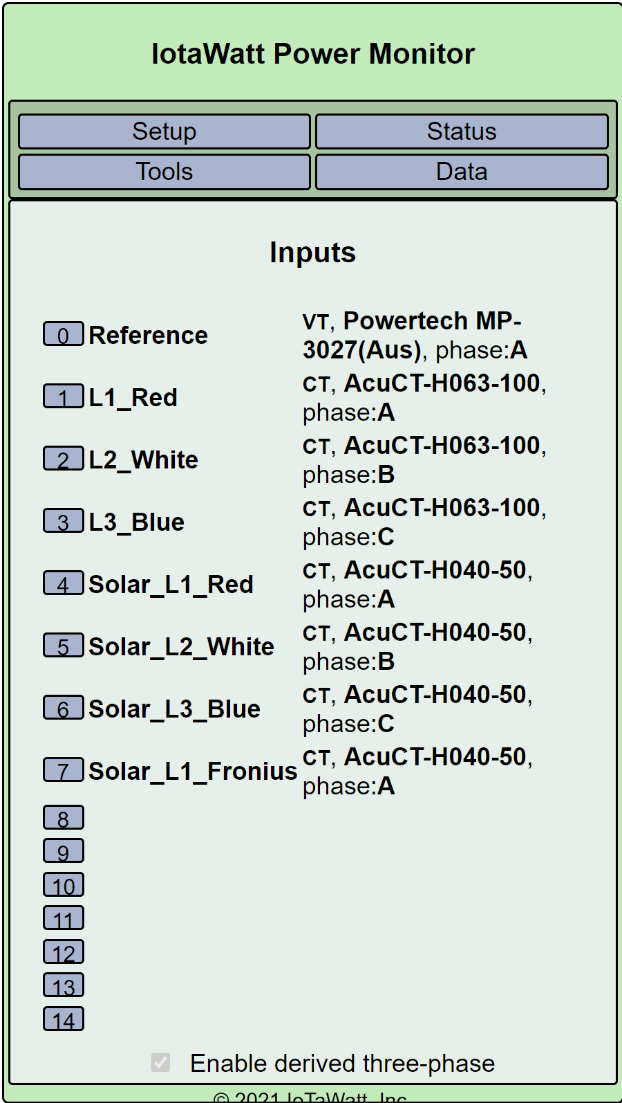
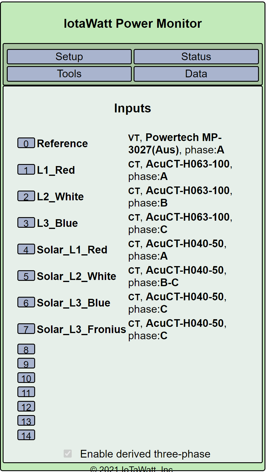
Um no. This is how the three phases are configured
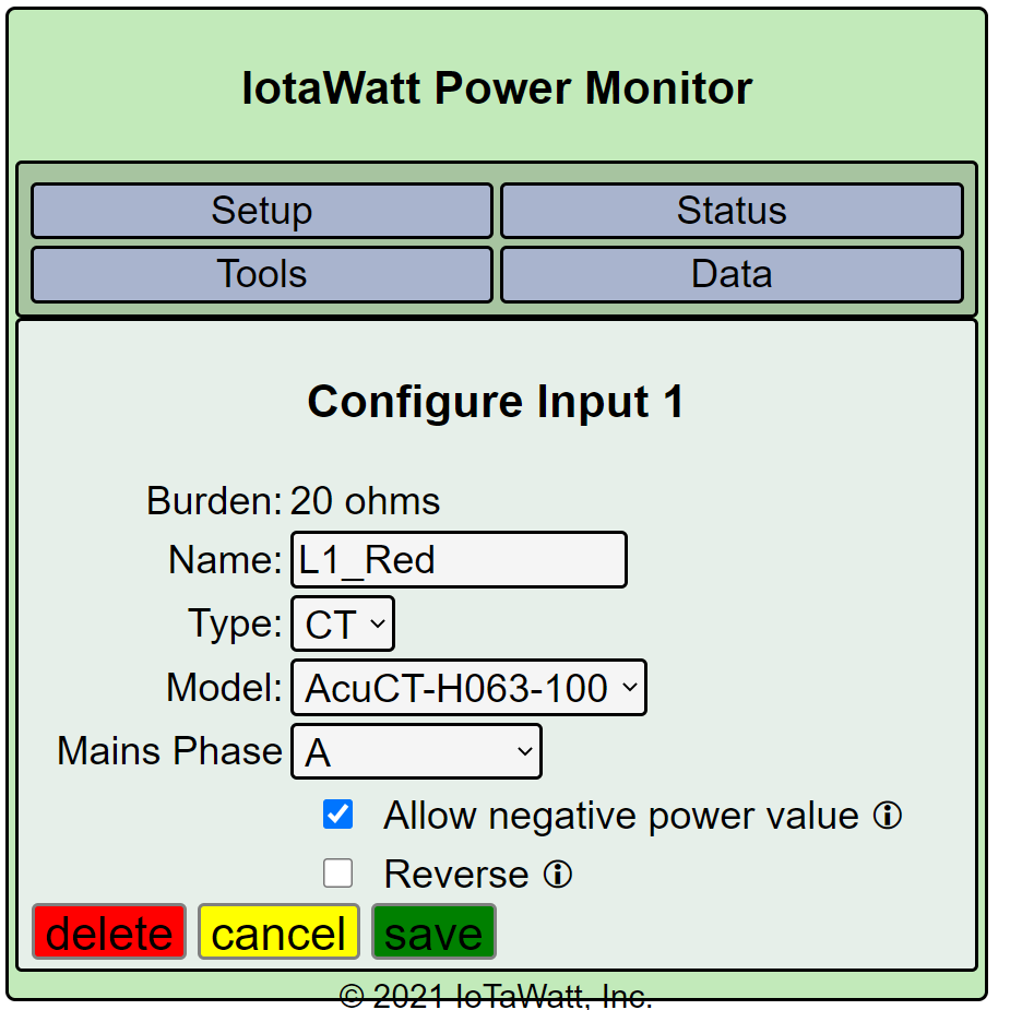
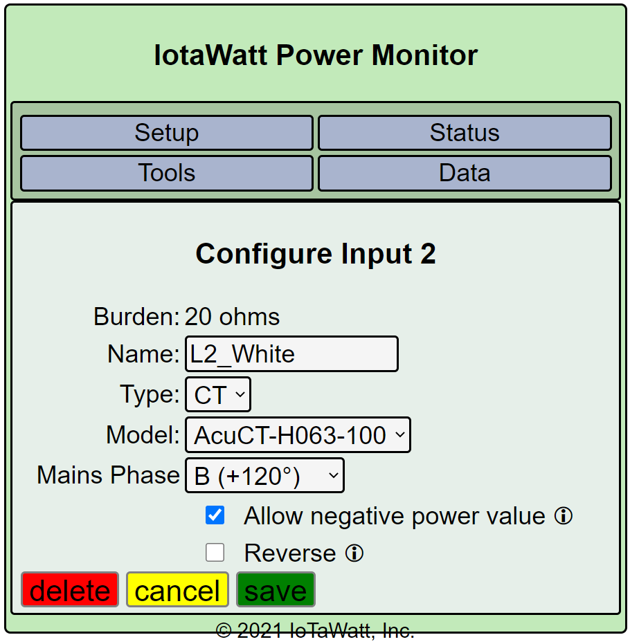
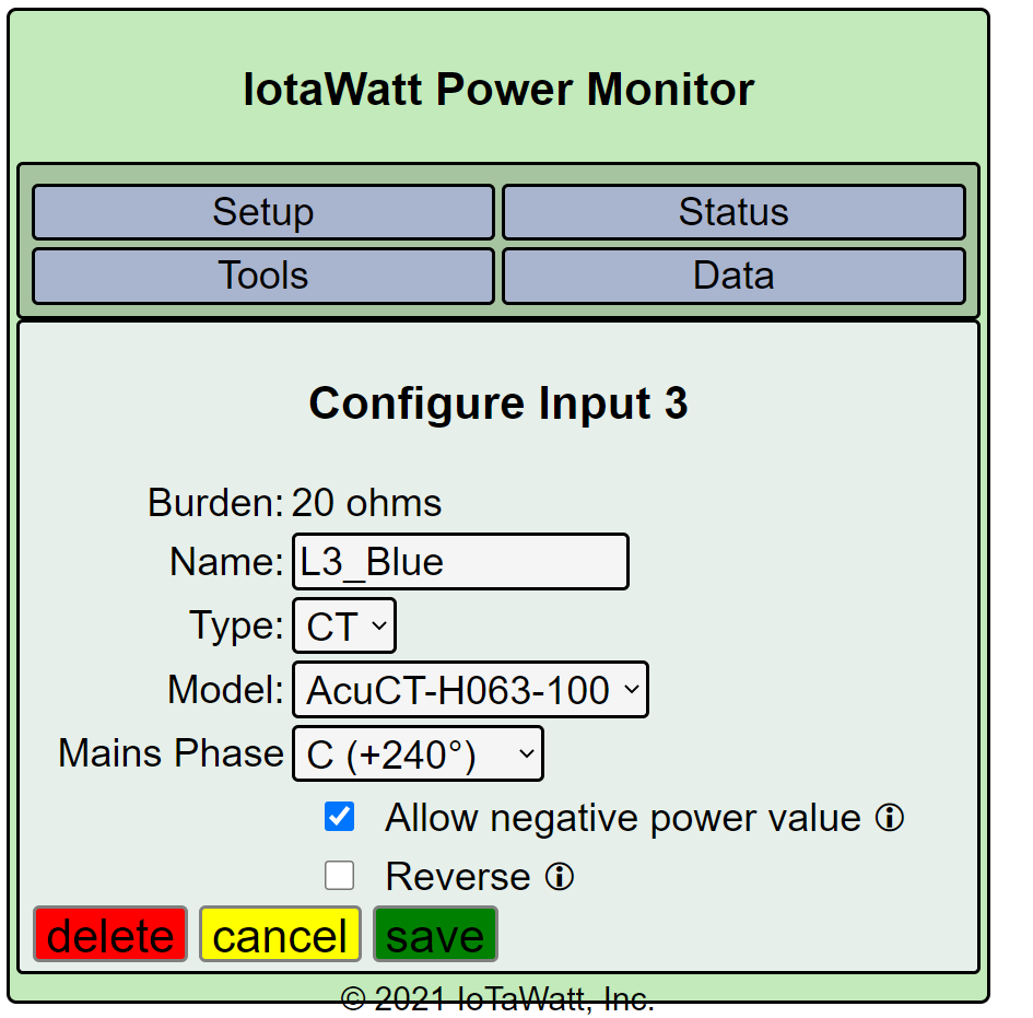
Allow negative power value is ticked for all of them.
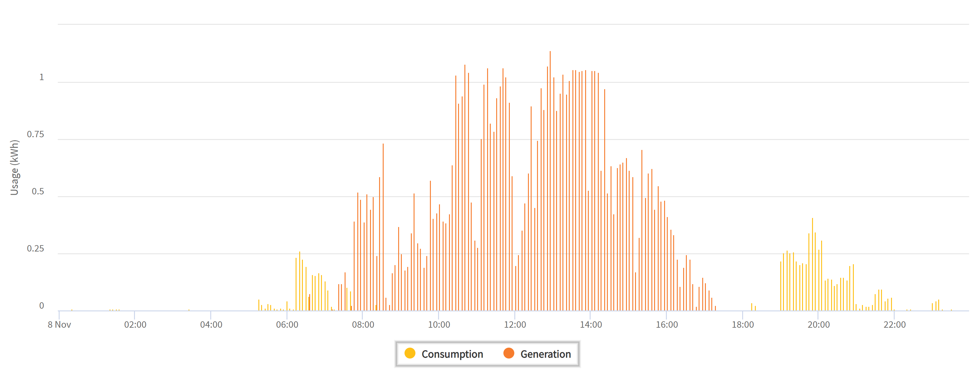
At the time I posted the snapshots of the Iotawatt, This is the 5 min meter data from my electricity retailer. Unfortunately, there is a 24 hour delay in it being available to me.
| 2022-11-08T14:45:00.0000000 | 0 | -0.643 |
|---|---|---|
| 2022-11-08T14:50:00.0000000 | 0 | -0.651 |
| 2022-11-08T14:55:00.0000000 | 0 | -0.669 |
| 2022-11-08T15:00:00.0000000 | 0 | -0.617 |
So your calculations are reasonably close 971w vs around 670w.
According to the five minute retailer meter data at that time, I was exporting only 669w (averaged across the five minutes). What I don’t know is whether the battery was charging at that time, which could account for the difference in your calculations and the consumption figure.
Looking at the current figures on the powerwall vs what my inverters are reporting, I can see that I am currently generating a combined total of 14,754w (inverter figures). The Powerwall is reporting that as 14.7kWh so it appears to be correctly setup. Assuming it’s consumption figure is also correct, I am currently using around 1000w. By comparison, the Iotawatt is out on the generation and consumption it would appear, so I haven’t got it right.
It is online, and managed by Tesla remotely. That said, it should be configured as per one of my early posts i.e. it monitors the three phase supply via CT clamps, but being a single phase inverter, is only connected to the L1 red phase (I confirmed this today when a Tesla rep came out to perform a QA Inspection on the installation). if it calculates that I am drawing from the grid across the three phases, it will supply the equivalent power back to the grid on the L1 phase to zero it out e.g. each phase is drawing 1kWh from the grid, it will export 3kWh back to the grid on L1 which tricks the meter into zero consumption as opposed to seeing the export as solar generation. This is why Iotawatt is simultaneously showing positive figures on L1 and negative figures on L2 and L3.
I should be seeing something being uploaded to PVOutput as I am not 100% self sufficient and am importing power from the grid at various stages during the 24 hour period and exporting excess to the grid:
Using my inverter figures and retailer meter data, yesterday I generated 95727wh from solar and exported 65815wh to the grid. I imported 8741wh giving me a total consumption of 38,653wh for the day. That should reflect in what’s uploaded to PVOutput if I have everything set up properly (which I don’t clearly).
Are you sure that’s true? Are you saying that the utility is reporting the 5 min kW average? Is it possible they are reporting the kWh measured for the 5 minute period? If that is the case, it would represent -0.669 x 12 = -8.028 kW.
You regularly mix Watts and Wh in your posts. Those are completely different metrics.
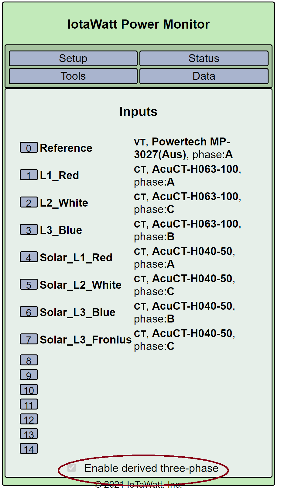
You had not even checked “Enable Derived Three-Phase”. It would be impossible to follow that procedure without that.

The phase assignments are clearly wrong. Power Factors of .48 and .52 are a pretty certain indication that the phases are wrong, moreover, swapping them would agree with what I maintain appears correct for the mains.
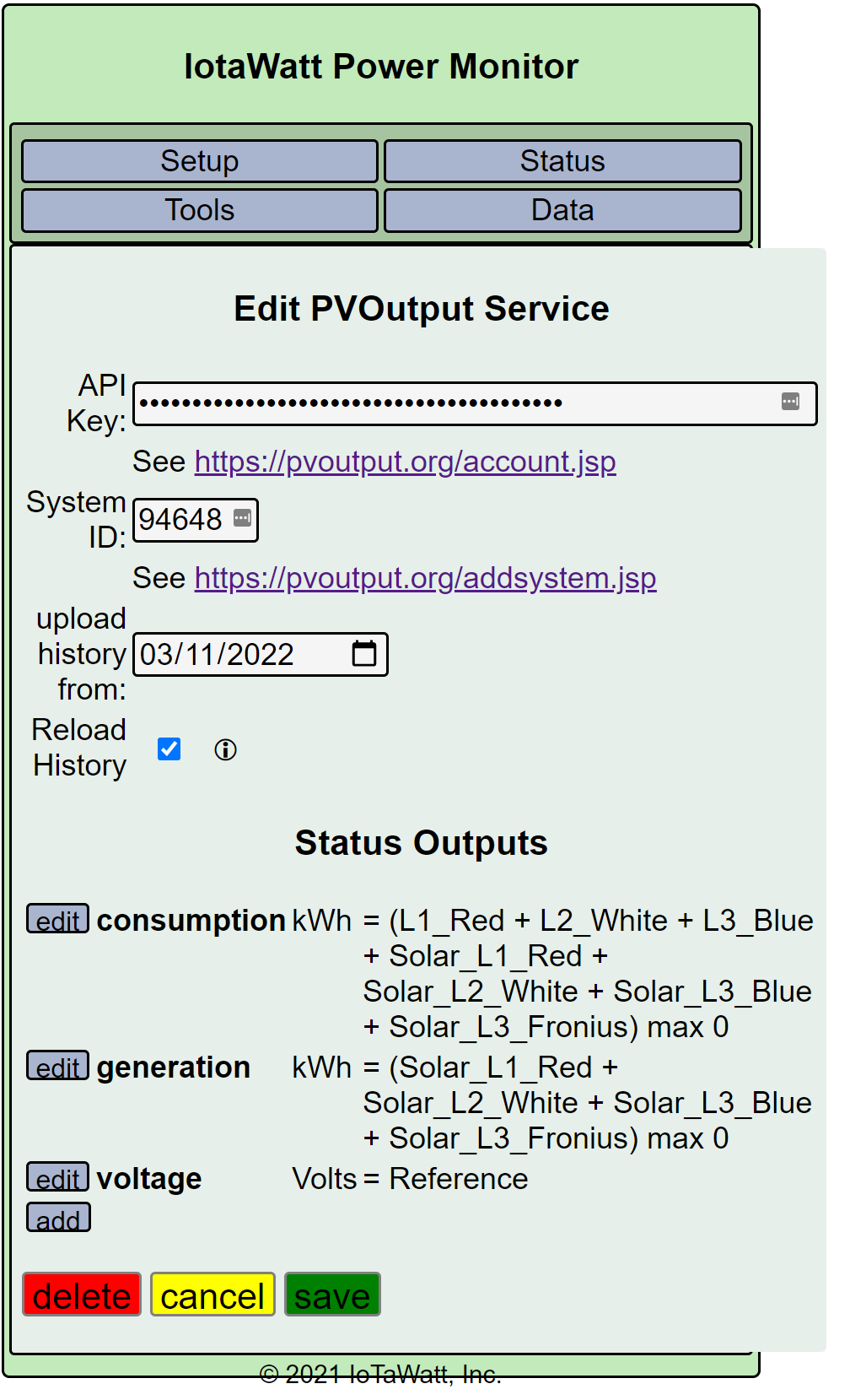
You have setup the IoTaWatt to upload the value of zero for consumption, generation and voltage, as I indicated with the circled outputs.
So, if you want to proceed, the battery must be incorporated if you are going to be able to reconcile everything. The first step is a line drawing that shows the mains, inverters, battery and load with the location of each CT indicated as well as the direction of the arrow on the CT.
Unless there is another place to tick the box, I ticked it after your first post advising me to do so. Still ticked, as far as I can tell.
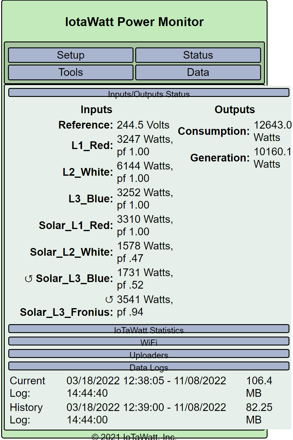
I’ve set up the three phases as per your instructions and changed the solar phases to correspond.
Is this looking better?
Without a line diagram of this system, I’m flying blind with assumptions that may be completely wrong. Moreover, the active nature of Powerwall 2 operation and any charge/discharge of the battery is outside of anything observable here.
In that context, the mains appear to be assigned to their appropriate phases, although I still maintain that they should probably be negative indicating export. If that’s the case, L2 and L3 should show as negative at night when there is no solar. Is that the case? Can you show a status display with no solar to verify?
Likewise, the phases of the three-phase inverter appear to be correct, and demonstrate my previous assumption that the three would be equal.
The Fronius inverter does not appear to have the correct phase assignment. It looked better when it was phase C.
It has no impact with correct phase assignment, but Solar_L2_White appears to be reversed. I would recommend fixing that.
Thanks Bob
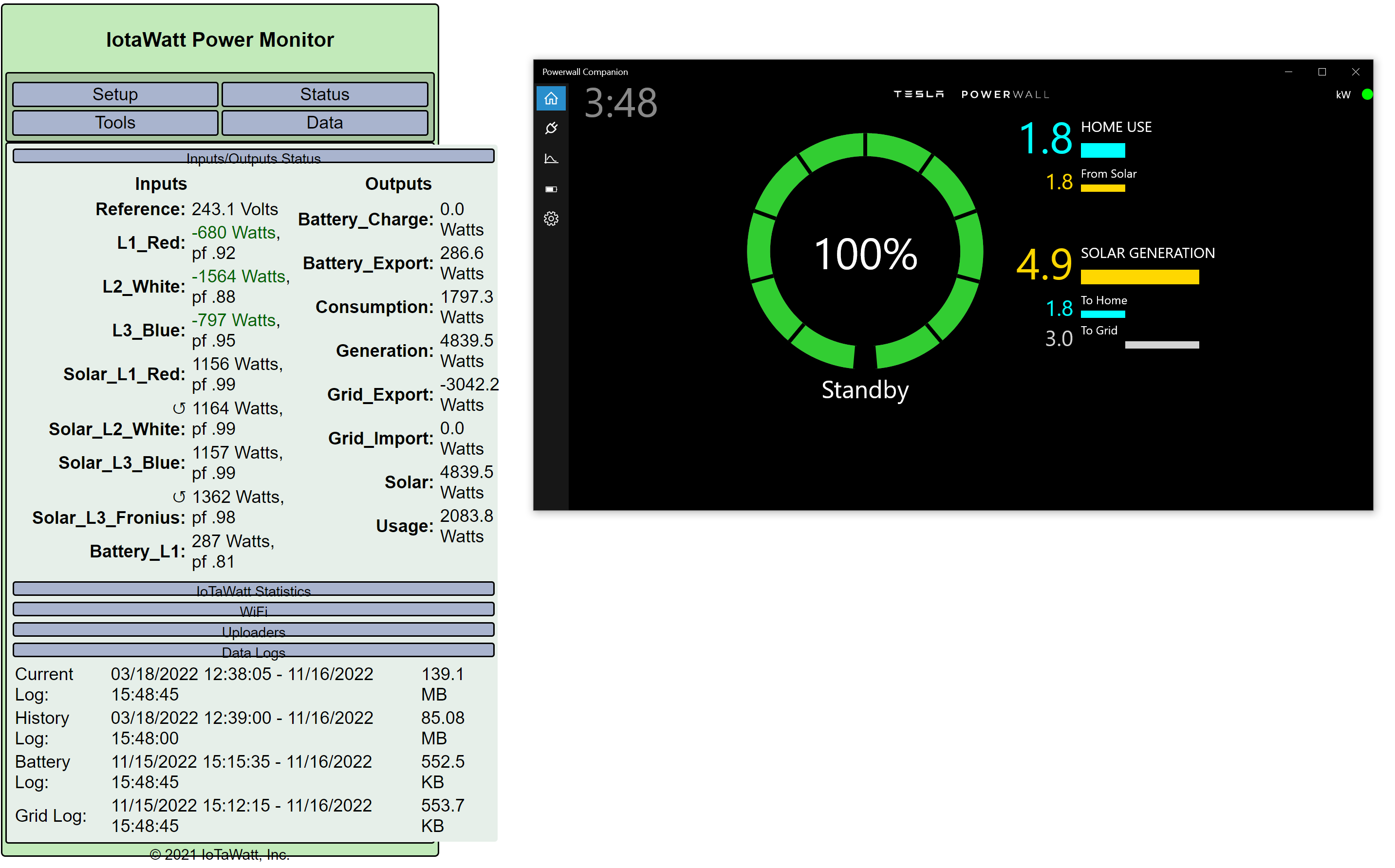
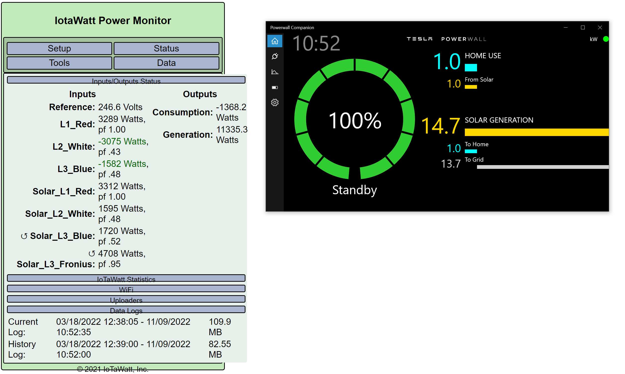
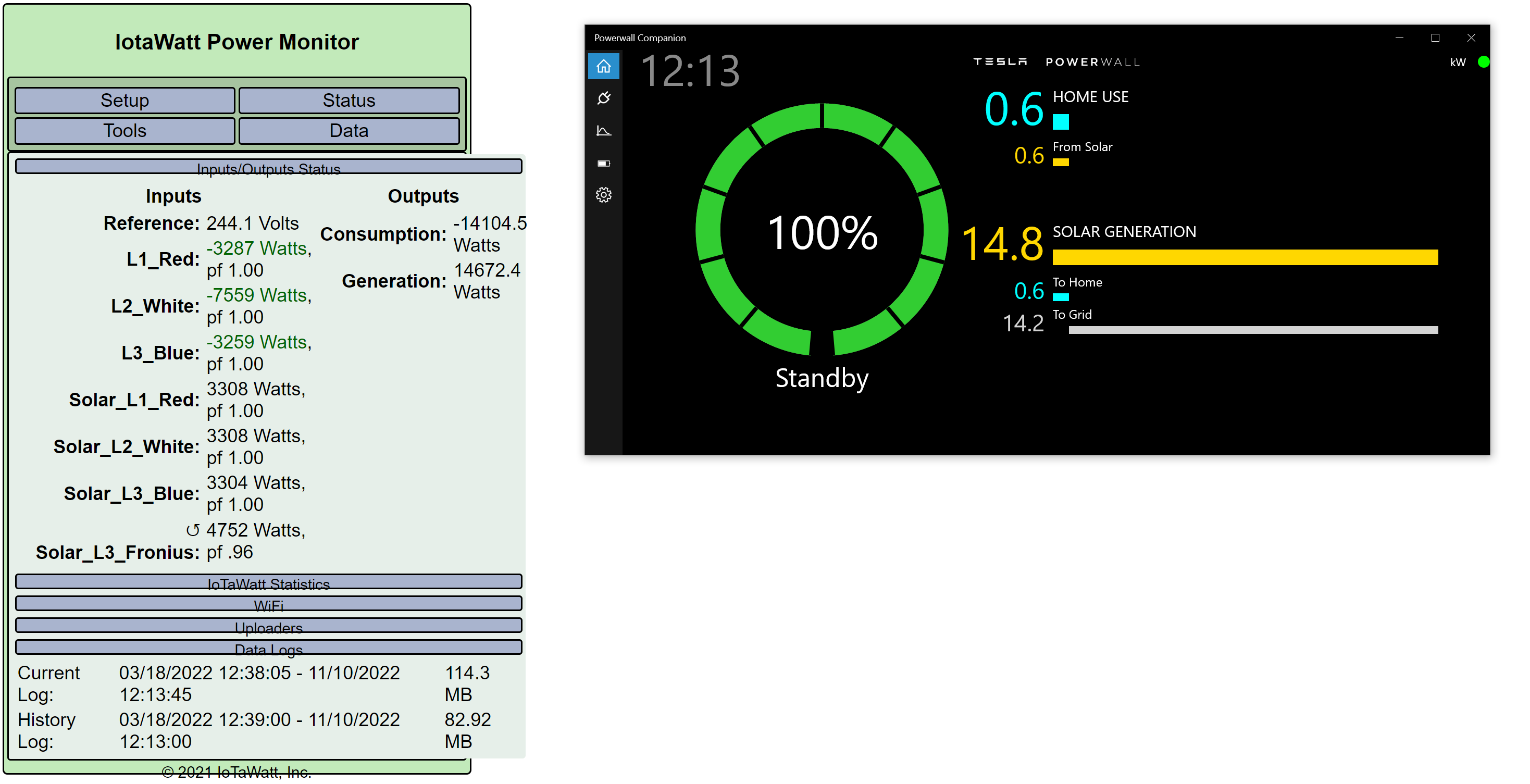
I made the changes you suggested and will draw up a line diagram when I get a chance. Please see below to see if I have it correct. For reference, I have included the PW data for comparison, although that would not be as accurate as the IotaWatt.
I will post another snapshot tonight to show what L2 and L3 are showing when there is no solar.
While I’m concentrating on getting the configuration right, before worrying too much about uploading the data, I did notice that the IotaWatt is now uploading to a Test system on PVOutput with about a 5kWh variance to the inverter figures on the production system.
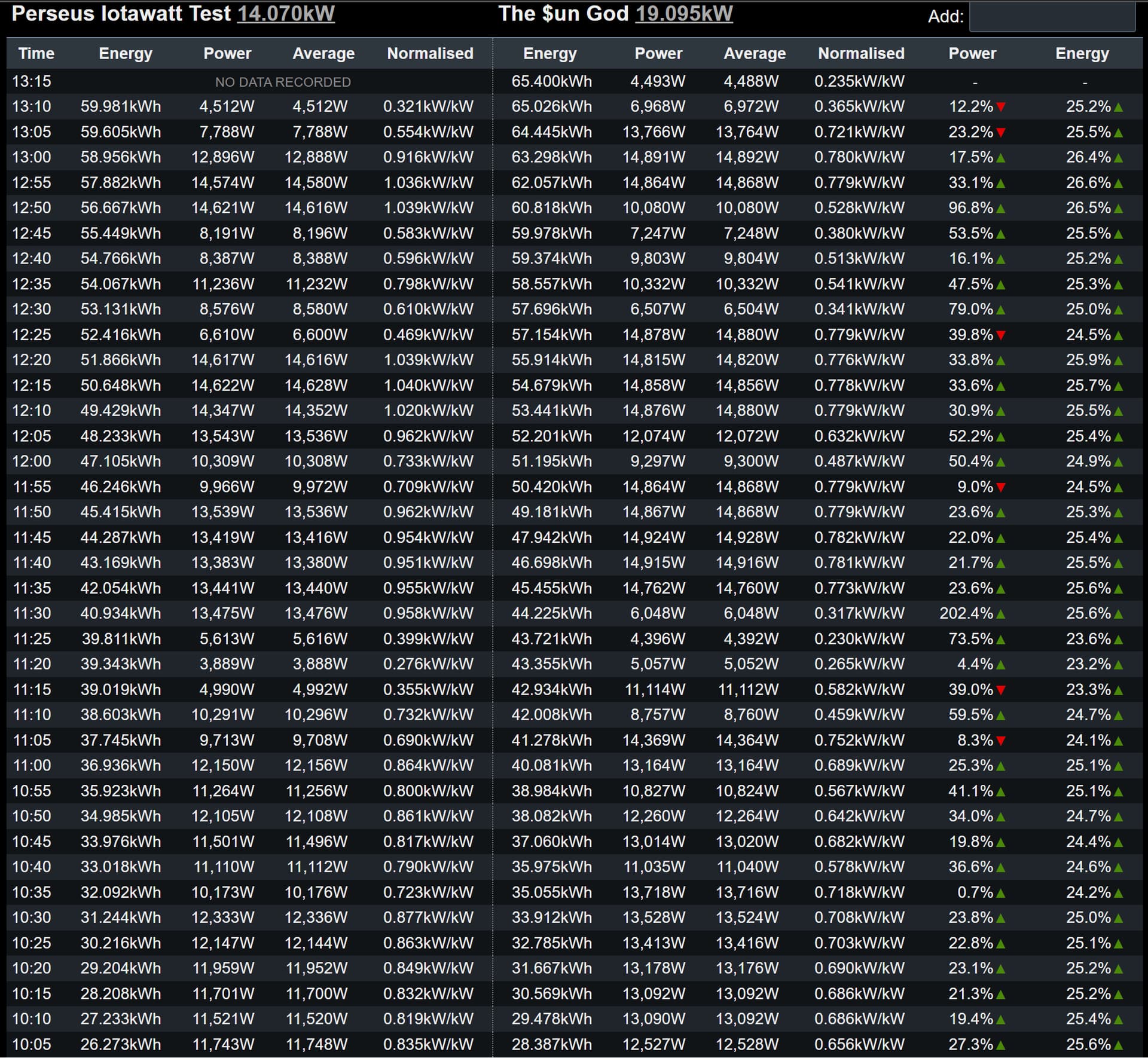
The consumption data is way off however for the test system. I know my daily consumption on average is about 40kWh and it is showing about 82kWh consumption at 1pm. The PW2, is showing a total consumption of 13kWh for the day so far, which is around what I would expect.
This is the config for PVOutput:

At some point you will need an integrator to separate import and export, but this seems to match the Powerwall Companion. What you are calling consumption is usually called Grid as it appears to be just the sum of the mains. The Generation of 14,672 Watts is within 1% of the 14.8 kW. I would compute consumption as the mains + Solar = 567 Watts. That matches the 0.6 in Powerwall Companion.
I’ll be curious to see how the Powerwall Gets the solar generation data. I’ve looked at the Powerwall 2 three-phase descriptions and only see the option for one solar CT. Three-phase or other inputs appear to use a data cable to a neurio. Is that what you have?
Again, going on assumptions, consumption to PVoutput should be"
consumption kWh = ( L1_Red + L2_White + L3_blue + Solar_L1_red + Solar_L2_White + Solar_L3_Blue + Solar_L3_Fronius ) max 0
Generation kWh = ( Solar_L1_red + Solar_L2_White + Solar_L3_Blue + Solar_L3_Fronius ) max 0
The max 0 is to ensure the numbers are positive. Inverters can use a few Watts at night for standby mode and that would appear as a negative number to PVoutput which will reject it outside of sunset to sunrise time.
Similarly, consumption could possibly be negative at night if the powerwall overcompensated during load fluctuation. If it overcompensates by a few Watts, the “max 0” function will force zero and keep PVoutput happy. Be sure to put parenthesis around all of the preceding calculation so as to operate on the result.
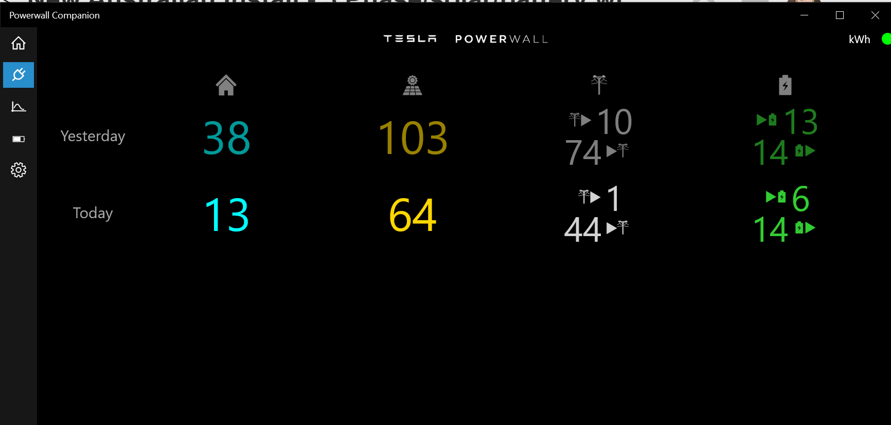
The Powerwall’s definition of consumption is the same as mine. It is the energy that your household consumes. In other words, what your meter would record if you didn’t have generation or a battery. Let’s look at what the powerwall is saying:
Your house used 13 kWh as of the time of the screenshot.
Your total solar generation was 64 kWh
So, you produced an excess of 51 kWh.
You imported 1 kWh from the grid and exported 44 kWh to the Grid, so your net export was 43 kWh.
You discharged (imported) 6 kWh from the Battery and charged (exported) 14 kWh to the battery, so your net export to the battery was 8 kWh.
13 kWh + 43 kWh + 8 kWh = 64 kWh
In order to make a comparison to the IoTaWatt you will need to wait for the current setup to be in place for the whole day. You will be able to get the net Grid but the in order to get the net battery you will need to put a CT on the cable connecting the battery to your service.
Once that is done, I’ll show you how to setup integrators so that you can get the Grid import/export and battery charge/discharge metrics.
I believe so. As you might have worked out by now, I’m no electrical engineer so my terminology might be incorrect at times. Talking to the QA guy that Tesla sent out yesterday to inspect the PW2, I mentioned that initially, the PW2 was only seeing the single phase inverter and using the solar production from that, so PW2 was capping my solar production at 5kW and missing the solar production for the 10kW inverter in the data it was displaying. This was because it hadn’t been clamped properly at the time of the initial install and this was subsequently rectified by the installer when he added additional clamps. I mentioned that the problem seemed to have resolved itself before the installer returned to add the additional clamps. and QA guy told me that the Gateway is smart enough to realise that if it is seeing negative flow through the mains that it will assume the negative flow is solar generation, irrespective of the solar clamp and calculate the data on that basis. He mentioned that when they log in as an installer, they will only see the data generated by the CT clamps and not the figures calculated by the gateway independent of the CT clamps. I don’t know how accurate the estimated data is but the PW2 is now clamped properly and should be reading the CT clamps for its data.
Thanks Bob. Much appreciated
I think I’ve got it right now. When I compare yesterday’s reading they are pretty close to the inverters and retailer figures:
Generation
(Inverters) 84.98kWh / (IotaWatt ) 84.96kWh / (PW2) 85kWh
Consumption
(Meter) 42.48kWh / (IotaWatt) 42.76kWh / PW2 42kWh
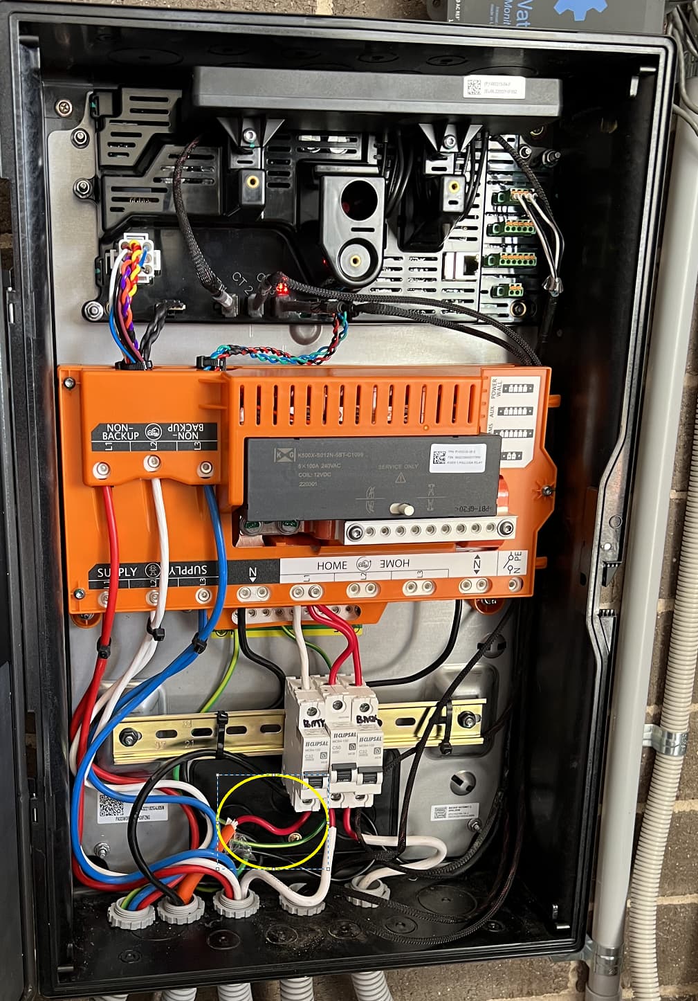
In terms of monitoring the battery, I’m guessing I need to clamp the circled red wire in the below photo of the gateway. That leads to the battery. Is that correct?
Pretty close?
Never got that line diagram. Here is a line diagram from the PW2 installation guide:
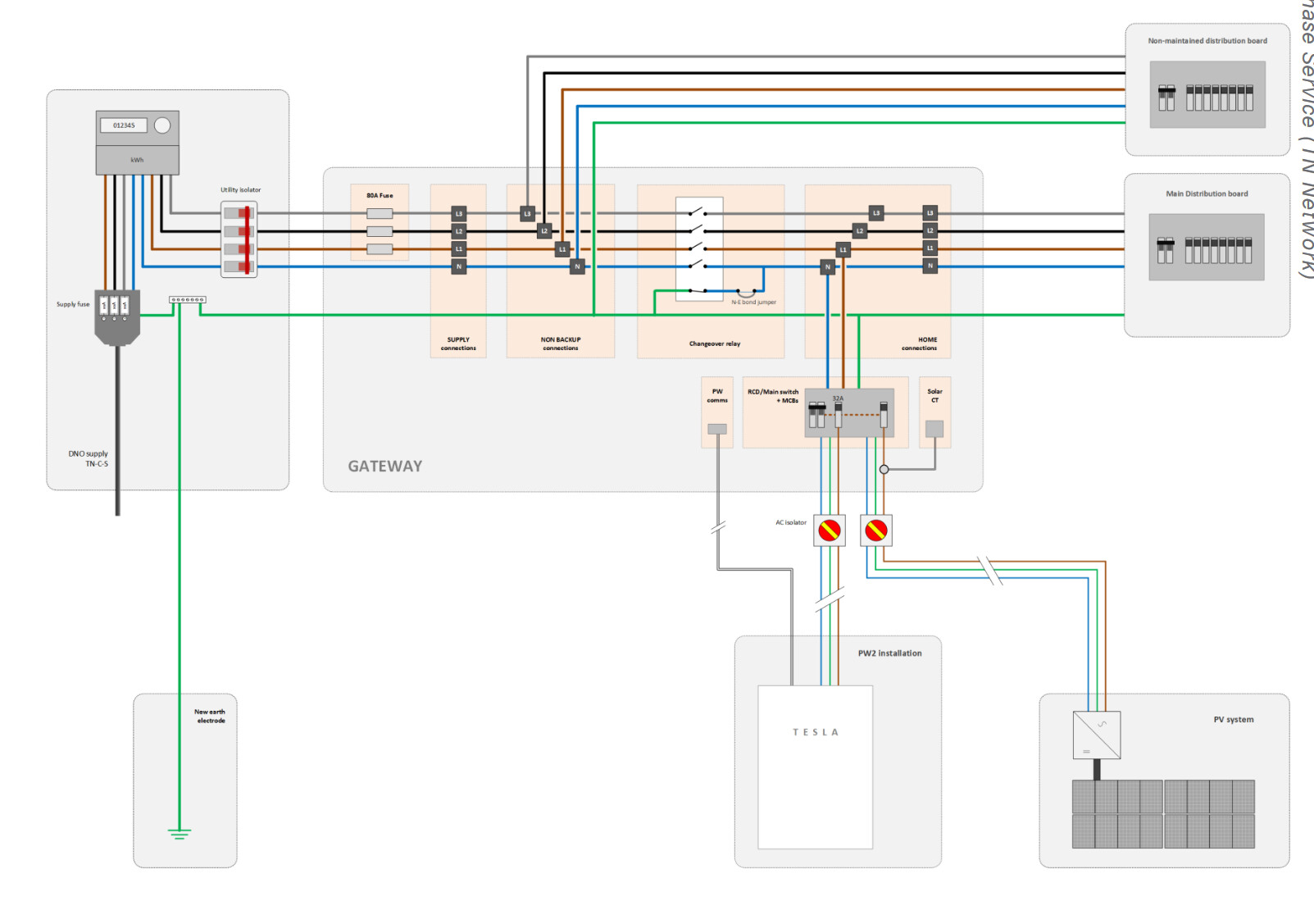
I’m guessing that the conduits in the picture are, from left: Grid in, Powerwall, Distribution board out, PE, and single-phase solar?
Your picture seems to show connections to the “non-maintained distribution board”. There doesn’t seem to be three phases going to a “main distribution board”. I suspect you have one distribution board and there is something different going on with the L1 phase because there are two white wires that appear to go to that board. Don’t know how that would work and curious if you have segregated L1 circuits, backed-up and grid.
To answer your question, if the second conduit goes to the PW then that’s where the CT should go. Name it what you please, but include L1 in the name for clarity and for this discussion I’ll just call it Battery_L1. The CT should be positive when discharging and negative when charging.
You should create two integrators:
- Grid = L1_Red + L2_White + L3_Blue
- Battery = Battery_L1
Now you can define some outputs:
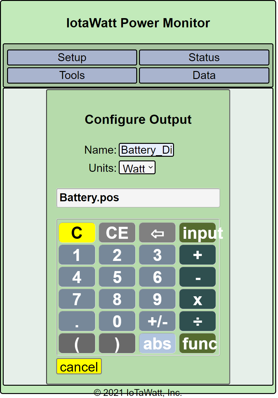
- Battery_Charge = Battery.neg
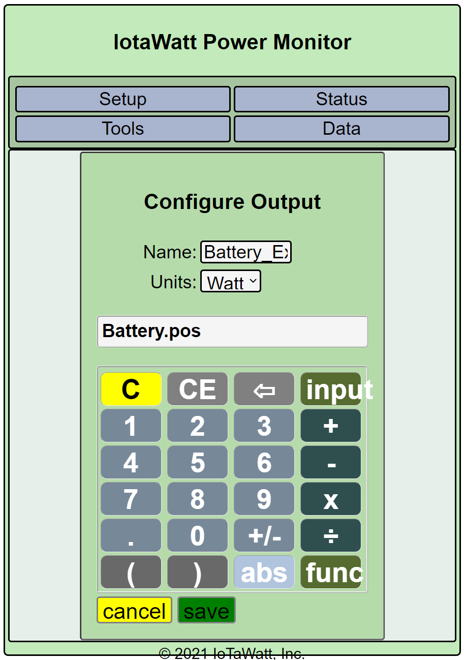
- Battery_Discharge = Battery.pos
Those should match the green Powerwall Companion [PWC] numbers under the battery symbol.
- Grid_Import = Grid.pos
- Grid_Export = Grid.neg
Those should match the white PWC numbers under the grid symbol
- Solar = Solar_L1_red + Solar_L2_White + Solar_L3_Blue + Solar_L3_Fronius
That should match the yellow PWC numbers under the solar symbol.
Usage = Grid.net + Battery.net + Solar
This is your actual household energy use, exclusive of any power being used to charge the battery but including power from the battery. In other words what your meter would read if you didn’t have solar or batteries. It should match the blue PWC numbers under the house symbol.
There is ore that you can do. You can create an integrators that will tell you how much solar is self-consumed, goes to battery charging, and exports to the grid. You can determine how much of the battery charge is from solar and how much is from the grid.
Firstly, a big thank you Bob, for your assistance with this. It is greatly appreciated.
Sorry, been a bit busy, will try to get to it soon for my understanding of how everything connects, if nothing else.
I think from left to right it is:
- Grid In,
- Powerwall Battery,
- Solar ( L1 and L3 wires connect to inputs on the gateway marked non-backup. L2 is marked differently. I assume that is the single phase solar
4)Powerwall CT monitoring clamps to main board
- Sub-Board (I’m assuming this is to power the essential circuits in the case of a grid-outage)
All I can tell you from my limited understanding of how this has been wired up is that all of my household circuits reside the “non-maintained distribution board” The PW2 monitors three phase grid input and the solar via CT clamps in the main board. However, as the PW2 is only a single phase system it is connected to the L2 (white) phase only for backup purposes, so all my essential loads (lights fridge etc) are on L2 and will be powered by the PW2 in the case of a grid outage. Ditto, the single phase inverter is also on L2 and can supply power to that circuit in the case of a grid outage. That said, you can see in the Iotawatt it is configured on L3 (Blue) and appears to be correct, so I’m now not sure. As far as I know, L1 (Red) and L3 (Blue) are only monitored by the PW2 and anything connected to those circuits, as well as the three phase solar inverter will not operate during a grid outage. I hope that I have not misunderstood your question. I will try to get my neighbour, who is an electrician, to look at this and confirm the configuration.
Done
I was able to create Battery_Charge but when I try to create Battery_Discharge it is not giving me the option to save. I can save it by calling it something else, like Battery_Export. It appears to have a problem with the name Battery_Discharge for some reason.
Another quirk. I created Solar as per your instructions but it didn’t appear as an input when creating Usage. I had to add all the solar inputs individually, but I think the net effect is the same.
I’d like to do that if you can tell me how to create the outputs.
This is how it is currently looking: