We have 4 panels in our house. Two 200A main panels fed off of the same 600A meter base + one 80A sub panel fed from one of these main panels + one Time-Of-Use panel (car & boat chargers) fed from it’s own 200A meter base. Then we have a 200A panel in my studio (separate building) fed from the 600A meter base. This is US 240/120v split phase bonded neutral. We will have solar but probably not until fall (waiting on Tesla Glass to be available in MN). The meters are located on the studio building so from the 600A meter are two 100’ 200A feeds (4/0 IIRC) and one 10’ 200A feed to the studio panel.
Initially I just want to play w/ IotaWatt and make sure that it will do what I want (also considered TED & GEM but didn’t anything to justify the higher costs of those) and get an idea of what a number of specific loads are doing. If this goes well then I’ll expand for permanent monitoring.
If I initially have one base w/ CT’s on the two 200A main legs of one panel, what happens if I place circuit level CT’s on circuits on the other 200A panel? Will it measure them accurately? Or will I need to instead do one panel at a time? I assume aggregate info will be off in this scenario and that’s OK for now.
Long-Term I assume I’d need 5 bases - one for each panel/feed?
Will the AccuCT 200A x 25mm fit 3/0 OK if that is what we have? Suggestions for larger CT’s for the mains? (The markings are not visible on either panel so I’m waiting on our electrical contractor to let me know what these are.)
The AccuCT 50A are good up to 50A? I don’t need to downrate them any?
The panels are already tight. Are there 20A, 50A, 70A and 100A CT’s that are smaller (I’m fine w/ non-splits) that are recommended and reliable?
The panels are flush in a sheetrock wall. For now I’m just planning to stick the base on the wall w/ some 3M temp tape and run the feeds out between the panel box & cover. For Perm I assume I’ll need to mount a couple of J boxes w/ conduits in to the panels? Suggestions for this welcomed.
You say they all branch from the same 600A source, so it should work fine.
You will need to figure that out based on what you want to measure and where those circuits are.
The 50A split core are all that I carry, but IoTaWatt supports a lot of different CTs. I used to carry Echun ECOL09 which are pretty small solid core 50A CTs. If you were going to buy say 50 of them, You could contact Echun and buy them directly. I can provide contact info and model details.
The enclosure has two mounting holes top and bottom. I’d recommend you bite your lip and put a screw in the wall. All the wires can make the unit pretty heavy and it’s a mess when (not if) the tape fails.
The 200A CTs have 25mm openings (1"). They should easily fit on your cables. I have 400A and 600A CTs with 36mm openings (1.4").
They are much smaller than the 50A ones here. But, they are not (rated) quite as accurate. They are UL listed, but don’t have TVS diode protection. They have much thinner wire, which is easier to fit in conduit when you have many of them. If you have 1/2" breakers these fit much better, but the 50A ones here also fit reasonably well. It just depends on how tight your panel is.
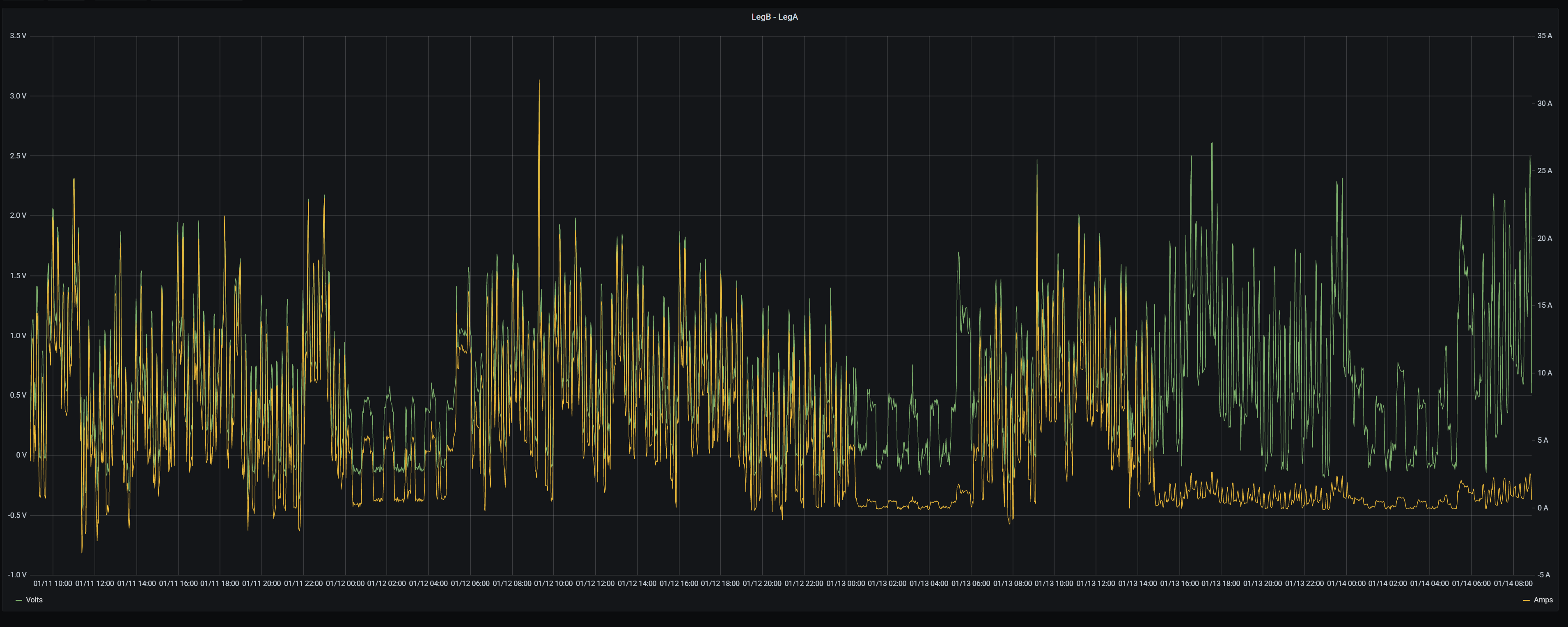
Since you have split-phase, you only need one CT. That is what I started with. I now have two IotaWatts and have one on each phase. Since I typically have unbalanced loads (my A leg is typically drawing 5-20A more than the B leg) the voltage on A is generally lower than on B (by 0.5 to 1.5V). Here is a graph:
This shows the difference in voltage between the two legs (in green) and the difference in current (in yellow). You can see them tracking very closely most of the time. The periods on the right side show how poorly my generator does with voltage regulation.
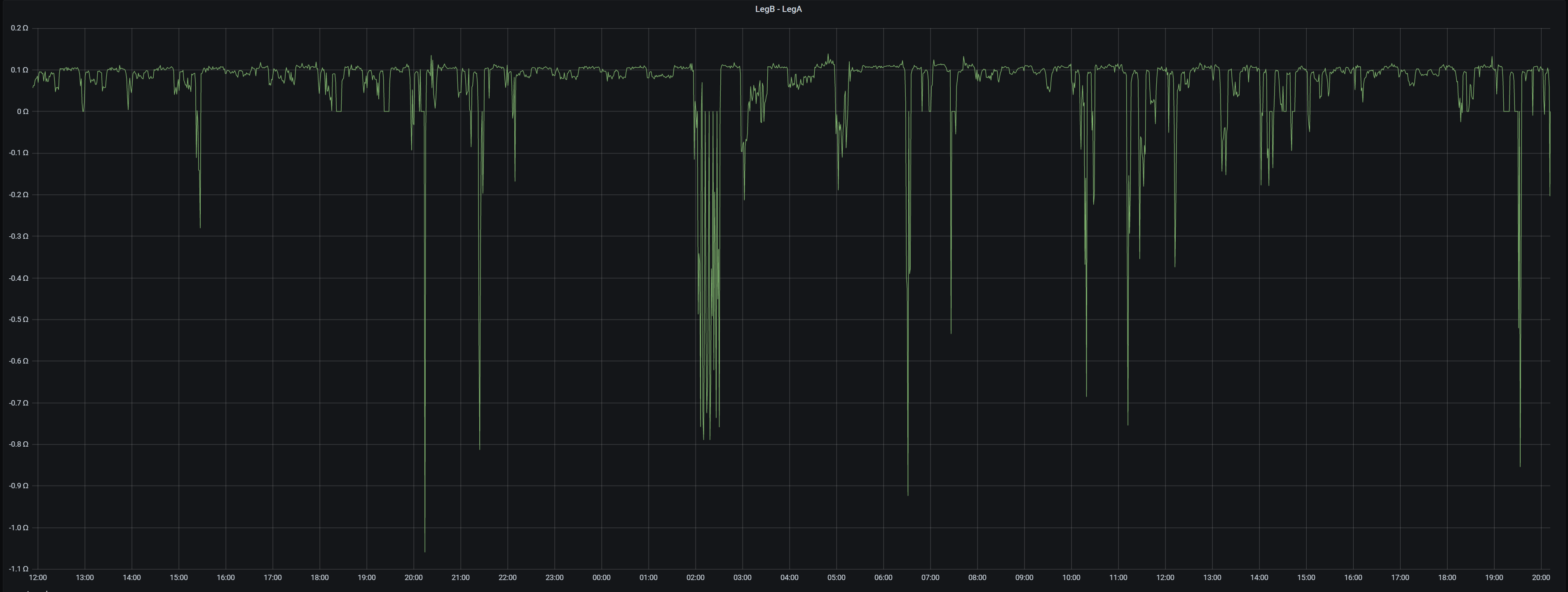
This one takes the data from above to calculate the resistance/impedance. As you can see, most of the time it is right around 0.1 Ohm which makes sense. But, sometimes it goes negative. This might seem weird, since there are no exotic components in my wiring (or house). But, this demonstrates an issue with using discrete sampling that is not synchronized. IotaWatt samples each channel about twice a second. Since I am using 2 IotaWatt devices, they are not sampling the channels I am looking at at exactly the same time. So, depending on the loads I have running there can be some significant differences.
Thanks for this. Great info. A couple of questions.
You say that I only need 1 CT (I assume for the mains). I would think I’d need at least 4 initially - A & B legs on panel #1 and A & B legs on panel #2 ? Then later add 4 more: A&B on Panel #3 and A&B on panel #4
How are you correcting for the voltage difference? How much impact does this have?
Perfect is the enemy of good. I talk about split-phase voltage reference here. Bottom line is the one 120V reference works well. Using two 120V references is more complicated and doesn’t help with the dominant 240V loads. I personally use a 240V VT calibrated down to 120V.