120V/240V split phase voltage reference

I’ve been monitoring my US split-phase service for two years now using a single 120V reference on one “leg” of the service. The results have been excellent, with overall and individual results within 1% of the utility meter and several revenue grade EKM meters on individual circuits. I long ago became comfortable with the notion of the single 120V reference, even though that voltage typically varies between 119V and 121V throughout the day with excursions even further off the mean from time to time.


I’ve measured the other leg, but that didn’t really provide enough data to satisfy my curiosity about the practical effects of some of the conventional wisdom that I’ve read about this. One of the warnings that I hear often is that when a transformer is shared with neighbors, their activity can adversely effect your voltage balance. I share a transformer with 5 other households, so I’m interested in how much stock to place in these warnings.

The US power system as delivered to residences, is not all that different from Europe and the UK. It is basically a 240V single-phase system, albeit with a center tap on the transformer for 120V circuits. We all think of it as a 120V system, because that’s what our light duty appliances and lighting use, and that’s what the wall plugs typically supply, but in reality, homes that use a lot of power typically use most of that power running 240V appliances like water heaters, pumps, clothes dryers, ovens, ranges, and air conditioners.

When those big loads run, they cause the overall voltage to drop at the load-center because of the resistance in the service entrance cables and somewhat because of the internal resistance of the transformer. The portion of the voltage drop caused by the resistance of your service entrance cable:

  • Effect only your home.
  • Effects both legs equally.

Whatever voltage drop is due to internal resistance of the transformer:

  • Effects all of the homes connected to the transformer.
  • Effects both legs equally

So all of the 240V loads in the neighborhood will cause a voltage drop that
effects both legs equally.

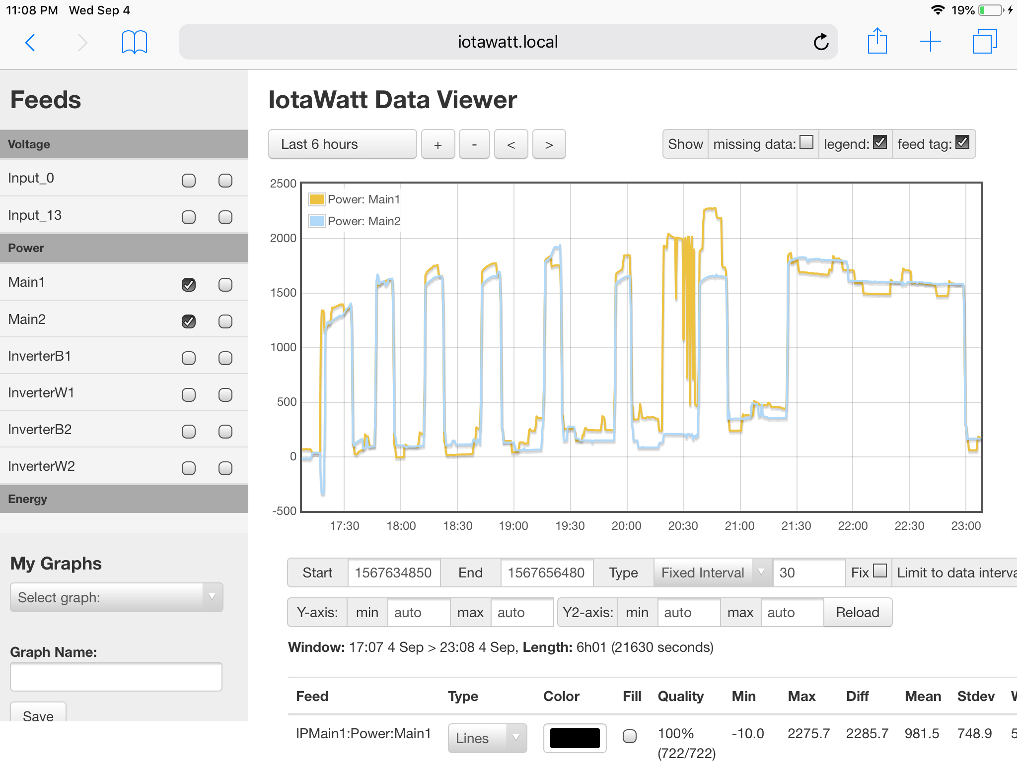
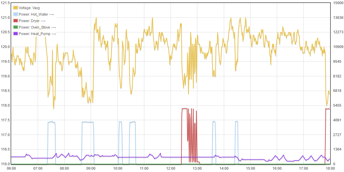
Here’s my total power for a day, contrasted with the total excluding the heat-pump, hot water, dryer, and oven/stove.

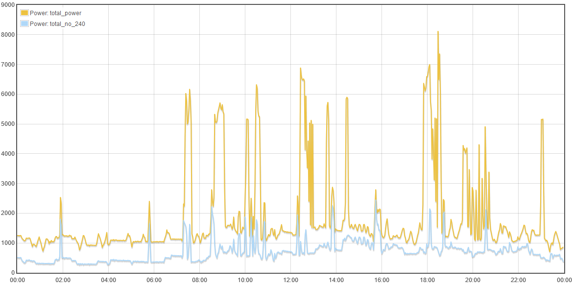
The 240V appliances account for 27kWh out of a total of 44kWh or 61% of the power I used.

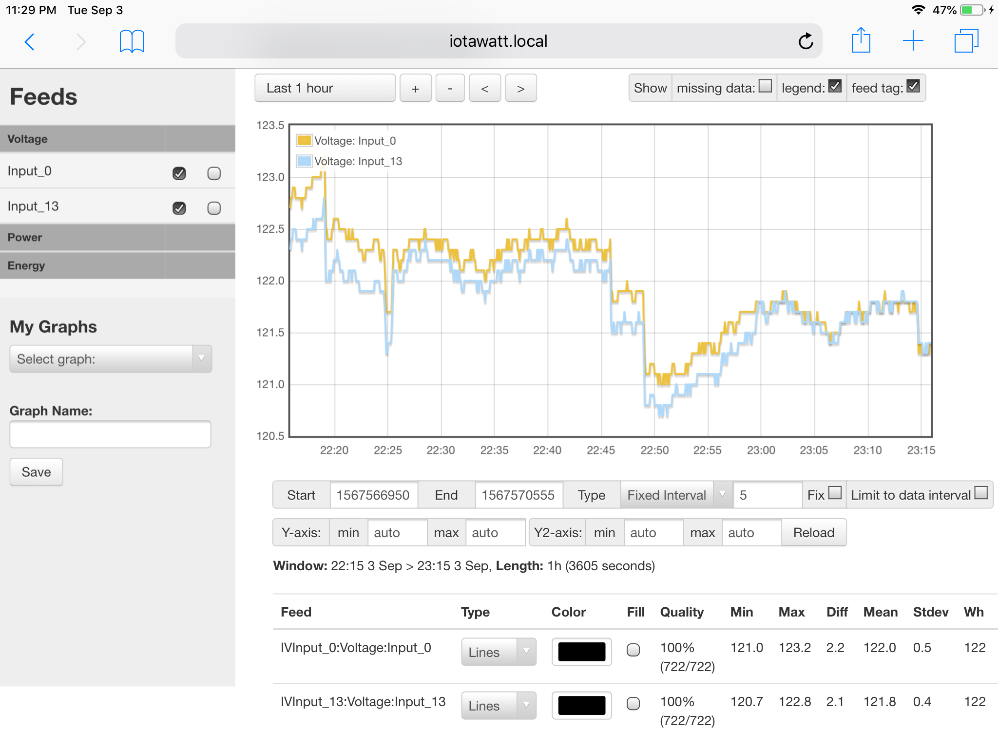
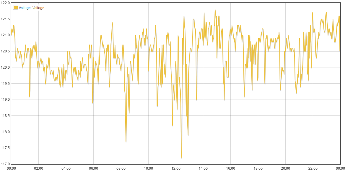
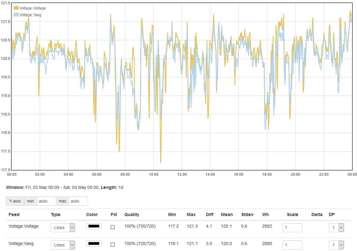
But this post is about voltage. Here’s my 120V L1 voltage for the above day (May 3, 2019)

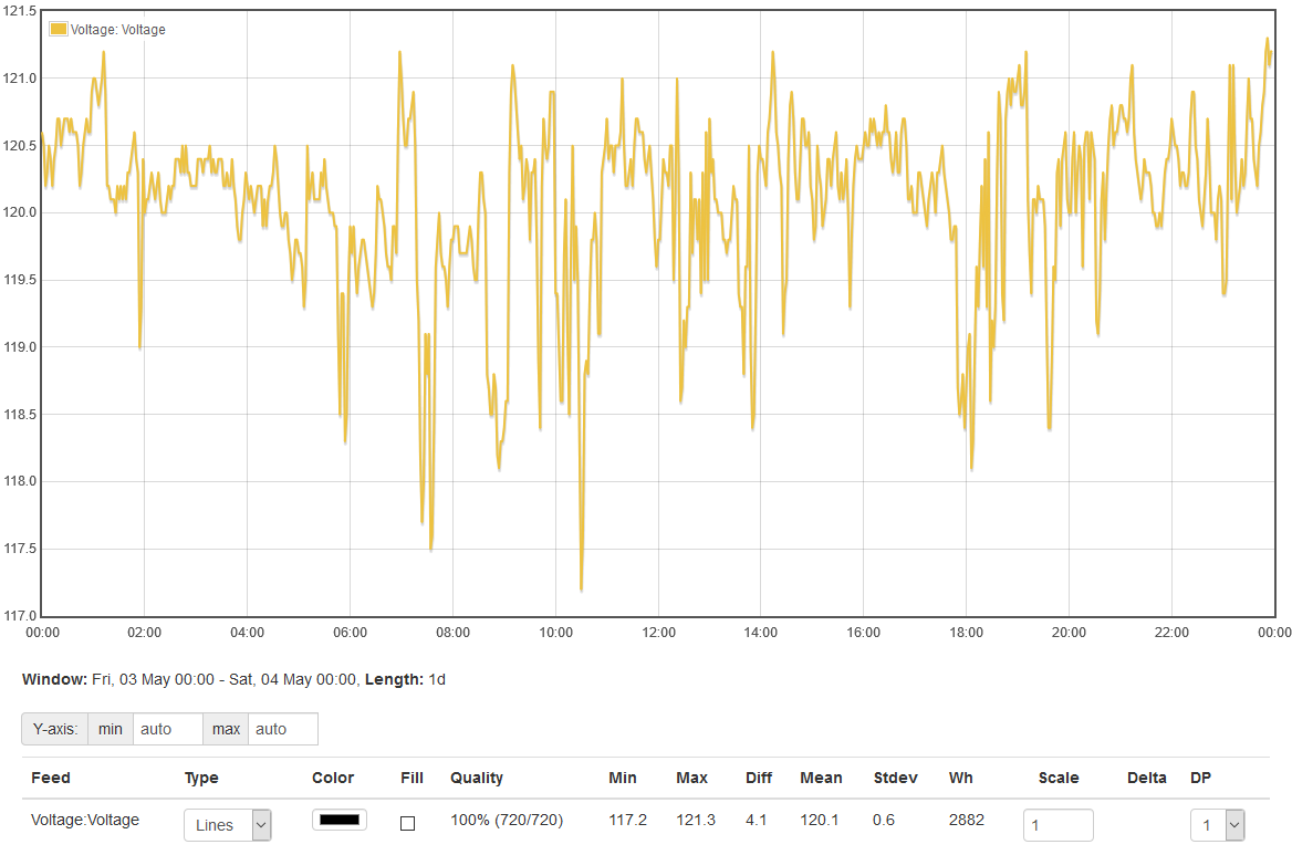
I included the stats line. It says the voltage varied between 117.2 and 121.3 with a mean of 120.1 (pretty good) and a standard deviation of 0.6V. So how appropriate is it to use this voltage to determine power for the L2 leg?

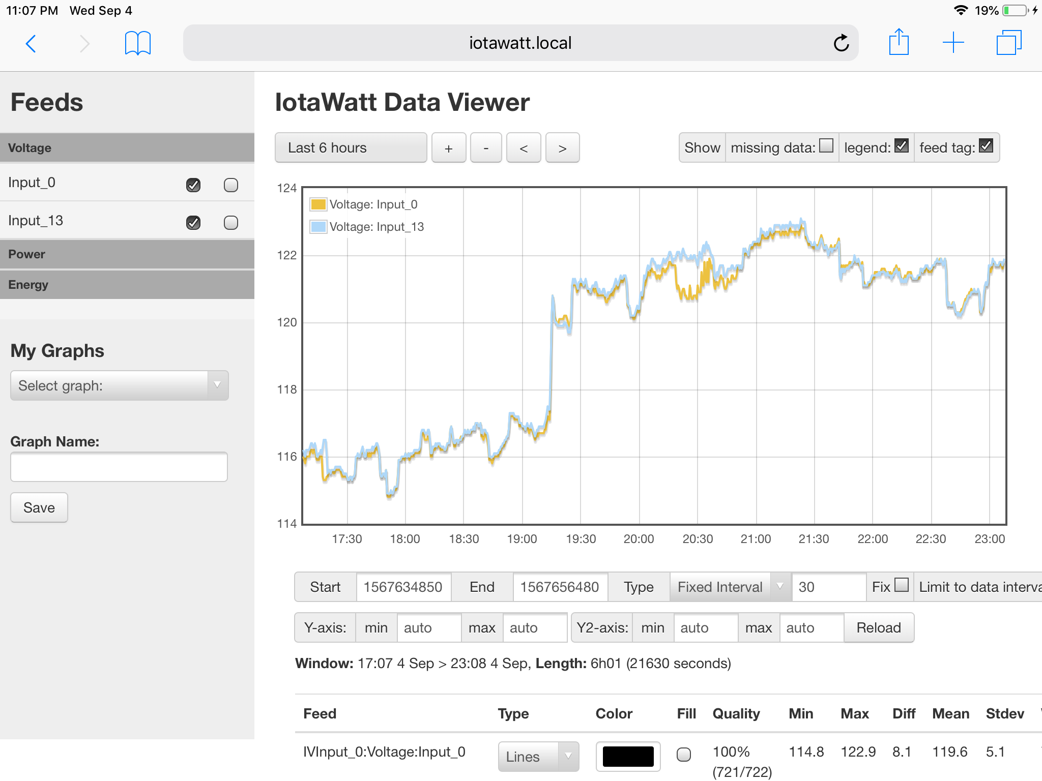
I’ve asserted that the 240V loads effect both legs equally, so awhile ago I added a 240V voltage reference to my IoTaWatt. I just installed a Euro plug and used a standard VT that I sell with the Eurowatt package. With a center tapped transformer, you would expect each leg to be 1/2 the total voltage. So here I’ve plotted 1/2 the total voltage with the L1 voltage:

What we see is that the L1 voltage varies almost perfectly with the overall voltage. Since L1 and L2 always add up to the overall voltage, we know that L2 will therefore also vary almost perfectly with L1 and the overall voltage.

Take a look at how the 240V loads are causing most of the low-voltage dips.

Remember, these 240V loads effect both legs equally.

There is some local variation that can be caused by an imbalance of current drawn between L1 and L2. That variation is caused by a drop in voltage of the high leg because of the resistance of the neutral conductor. This effects both legs equally opposite. That is to say that if one leg drops 0.5V because of a 120V load, the other leg will increase 0.5V. But for all intents and purposes, there is little effect on the per-leg voltage of the neighbors.

To illustrate this, here’s that same day’s voltage plots with most of my 120V loads. You can see clearly that the only place the L1 voltage varies significantly from the overall voltage is when there is a significant 120V load.

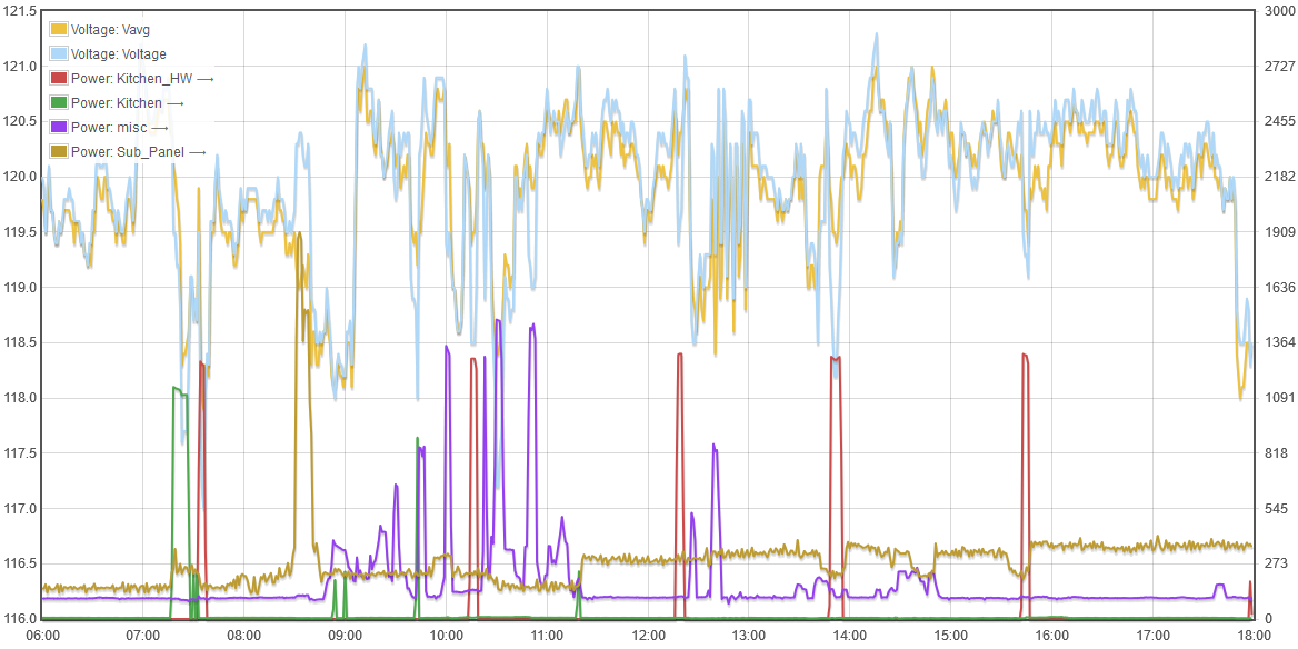
So if the 120V loads of my neighbors had any effect on my voltage, I think I would see it here. There is no evidence whatsoever of any significant single leg voltage variation that cannot be attributed to my usage.

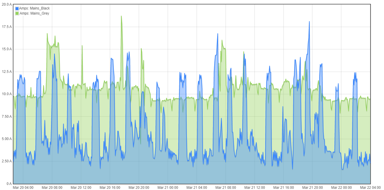
For a final perspective, here’s a plot that shown the voltage variation from average along with the current imbalance in Amps between the two legs:


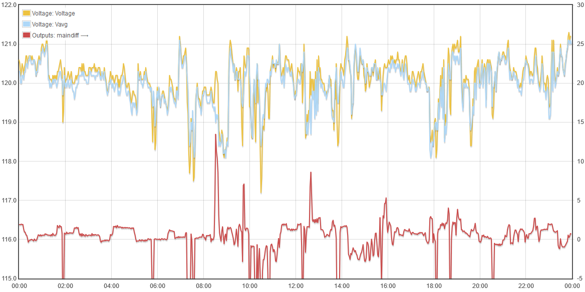
You can see where the imbalance is typically less than a few Amps, but where there is a significant difference, the L1 voltage deviates from the median.

So my conclusion is that with a split-phase US circuit, the loads of neighbors sharing a transformer will not significantly effect power measurements that use the voltage from a single leg as reference.

A secondary conclusion is that rather than use a 120V reference and doubling for 240V sampling, it would be more accurate to use a 240V reference and halve it for 120V sampling, thus splitting the difference for 120V imbalance and being exactly accurate for the dominant 240V loads. Unfortunately, that would be much less convenient for most users.

5 Likes

Very interesting and detailed info here @overeasy. Thanks for your perspective and ideas.

I can say that I also see a drop and rise in voltage between 114v to 126v and usually see some when my solar kicks in (240V in rush) and, as you said, when I use any of my 240v loads such as well-pump, dryer, and range/oven. On more quiet days when there are fewer 240v loads, I often do not see much fluctuations. We have a shared transformer on the street with two other homes and also live on a main branch (a 15-13 or something like that). At one time we had some potential back feed questions as the home across the street is from the 1690s and the wiring is very old, but it was later determined to be a loose neutral from the previous owners who were experimenters with electricity.

Hello, I want to purchase iotawatt to monitor my home power usuage. I am also using 2 240v grid tie inverters that I want to monitor so I see I need 4 cts… I also would like to monitor my home usage by using a 240v reference due to using 240v reference being more accurate when legs are unbalanced…The grid tie inverters act funny when legs are unbalanced aswell so this is why I want to more accurately measure my split phase main panel…
So my question is; can I use the euro 240v Vt and wire that Vt directly to a 240v breaker…and then also is there a way to calibrate the iotawatt so it only uses half of the voltage reference cuz the cts on each mains are actually reading 120v loads?

Sure you can do all that.

The way I connected a euro plug 230V adapter was to get a euro power strip from Amazon, then I cut off the plug and installed a US 240V plug (one of the blades is horizontal). Then i wired a mating 240V socket next to the panel, connected to a “pure” 240V breaker.

To use it as a 120V reference, first configure as the nameplate model and calibrate it to your 240V. Then divide the resulting calibration factor by two and save.

Solar inverters only need one CT if they only use two wires (no neutral).

Thanks so much for quick response…I already have a 240v breaker sitting in main panel with nothing attached to it…hey I gotta cook on the grill brb…yeah I’m just going to use 4 cts total…2 for the mains and one for each inverter?

u said to divide by 2 and save. Will the Vt keep sending a constant voltage signal that changes the voltage that is divided by 2? Is there anything not good about doing it this way? Wonder why Agnes didn’t just use the euro Vt u sell?

Should I use the same cts for the inverters?
I’d suppose 1 of the vts wires to one leg and 1 wire to the other leg and the 3rd wire to ground?
Last question…would I purchase the euro bundle or what should I purchase,I live in North America Split-Phase

The VT will always send a signal that is proportionate to the 240V of your mains. Dividing the calibration by two will cause the IoTaWatt to interpret that as half, or nominally 120V. The only thing not good is that it’s extra work and expense.

Typically 200A CTs for mains and 50A for inverters.

The VTs only have two prongs (120 or 240), no ground.

Probably order the NA bundle and add a comment to substitute a 240V VT.

For my nickel, I’d go with the 120VT. The only reason I have a 240 is to look at the results and confidently recommend the 120.

Is the only extra work wiring the vt to a breaker instead of plugging it in? How much more does the euro vt cost?
Reason Im thinking I shouldn’t use the 120v vt is due to having limiting 240v inverters supplying a Split-Phase panel…the inverters can slightly overfeed-backfeed-underfeed when legs are not well balanced…so I’m trying to figure out exactly how much unbalance makes the 240v inverters not supply power correctly. If I was using 120v vt during the unbalance I would not get the most accurate reading I could. During unbalance is when I really need things to be accurate…say the unbalance was 2000w from several extra loads on one leg. That’s around 20 amps and then also say the volts between legs are off by 2 volts then that’s 40w right there that would confuse the results on the graph during unbalance therefor not helping me see what the 240v inverters are doing during unbalance

To be precise, you would use two120V VTs and put 2 CTs on each inverter (total 4). Then specify a different VT for each of the two CTs on each inverter.

You would make that 240V circuit breaker connect to a duplex outlet with each socket a different leg and using the common neutral. That way each VT measures one of the legs.

1 Like

Wait I thought I could just use one 240v vt for the two cts on my mains and connect that vt directly to a 240v breaker …owe I see u meant to have the most precise measurements. Can more than one vt be connected to one iotawatt unit? Doesn’t matter I guess cuz I’m not getting 4 vts…I could see me paying for 2 of them but not 4…u did say that using a 240v reference and halving that is better-more accurate for split phase Na power supply when loads are unbalanced correct? could I just use two 240v vts, one for both mains cts and one for both inverters cuz inverters share a common output coming out of the subpanel the inverters are connected to? Does the Iotawatt allow for voltage references from two different Vt devices?

You can.

Yes, up to three.

Slightly better.

I don’t see any advantage to that.

Yes, you can specify the VT associated with each CT. That’s how three phase works but you can just as well use it for the two legs of split-phase.

You will recall I recommended just using one 120V VT. I still think you should start with that. If it turns out you have a unique problem with imbalance and two inverters, you can always add another VT to get more data.

I ended up getting two 120v Vts to monitor each leg of Split-Phase panel. This pic is showing a larger voltage difference due to a 400w higher load on one leg (input 13) due to a pool pump and at 23:00 I shut off the pool pump and voltage equals back out.
Therefore making me assume that if legs loads are more unbalanced (like having a 1000w micro on one leg) the individual legs voltages would be even more different from each other…
Legs could be unbalanced easily, so I’m glad I got two Vts to read more accurately.

2 Likes

I just want to point out that the entire range of this plot is 3V which is 2.5% top to bottom. The big swing at 22:25 is a 240V load as evidenced by both legs dropping the same amount. Although it may be caused by another user on the transformer, it would have no effect whatsoever on the accuracy of a single VT IoTaWatt.

The variation caused by the 400W pool pump looks to be about .25V. That’s 0.2%. So it would cause a very small variation in power. In the case of the pool pump, less than one watt.

I think the way these VTs are tracking your voltage right out of the box is phenomenal, but want to caution users not to get carried away overly complicating this. As much as this proves that the voltages vary, it demonstrates that modest imbalance will not cause your power measurements to be misleading.

I agree with everything u said…
Loads could also be unbalanced let’s say as much as 2000w instead of 400w which I believe makes my volts vary as much as 2v instead of .25 so the amount not read correctly could be as much as 34w in extreme cases…that would be 17amps (x) 2 volts. The 17 would be the amount of amps needed for 2000w and the 2 volts would be the difference in the legs voltage due to the unbalanced legs… I’ll get a pic tomorrow with very unbalanced loads…But again I agree that using just one voltage reference is very accurate…

seems to be more like 1volt difference which would only be like 20w max during highly unbalanced loads

Bob, is there an impact to the power factor calculation if you have a voltage imbalance on a split-phase service? I think that might compound the energy accuracy. A slight shift of the neutral point perpendicular to the 240V vector would mean the 120V reference voltage sees roughly double the phase-shift relative to the other leg.

I’m not sure what is going on with my system that is impacting accuracy, but I think the combination of solar and multi-tenant utility transformer is part of the issue.

I assume if the majority of (active) loads on a panel are 240V then you are better off with a single 240V reference, and if the majority is 120V you would be better off with two 120V VT’s; is this correct?

This isn’t the best way to address your accuracy problem. IoTaWatt is always much more accurate than you are reporting and these things ALWAYS end up being a configuration issue. I’m willing to try to resolve this but as I said in another thread, I don’t have a context to understand your setup, so I asked for some simple information as a starting point.

https://community.iotawatt.com/t/checking-accuracy/4503/6?u=overeasy

overeasy, after configuring my unit, learning some interesting insights and reading as many posts as I could find around monitoring one leg, each leg, or 240v, I’ve drawn some conclusions.

My older home with multi-generation wiring, etc. has quite and unbalanced load between split-phases and this is in winter before we start seeing voltage dips on some circuits below 106 in summer with A/C etc. as reported by my APC UPS devices.

I have little appetite right now for much re-balancing activity and am just finishing up my lab/network closet which I repurposed an old dryer circuit to a sub-panel with a direct ground run and 2 x 15A breakers, one for each leg. I could re-configure to allow for a 240v VT but have little other purpose for 240v in the lab.

Since I’m already down the rabbit hole here and having fun, what would you do if you were me and were already committed to either adding another 120v VT or switching to a 240v VT? I am using the single CT with the U loop method on 3 240v circuits.

This screenshot is with little use right now, just to show the config (mains phase delta hits 15-20 amps often, periodically 25+ and really causes the circuit to mains load delta to grow to 5+amps):

This is typical winter usage:

Thanks.

What are you trying to achieve?
My house typically has a KW more on one leg vs the other. This is not a problem. Even 5KW more on one vs the other is not a problem. If you regularly have 20KW more on one leg with standard residential service, it might be worth considering moving some of your grow lights or Bitcoin miners to the other leg (or running them on 240V).

Unless all of your loads are 240V there will be an imbalance most of the time. It is perfectly normal.

If you are concerned about accuracy, the difference (between legs) is likely about 1V at most, most of the time. That is less than 1%, which is about the long term accuracy you can expect.

I have 2 Iotawatts and I have been measuring the two 120V circuits for a long time. The data show that the difference between the legs is HIGHLY correlated to the current difference, and that it is typically less than 1 volt different (this is with a 10A or 1.2KW difference between the legs). The mean difference is about 0.5V. You will probably make the same decisions with data that has this accuracy than you would with data that is 10X as accurate.