Hoping to get some advise as to how many and what CT’s to buy. Was looking at 2x50A ones to go to the RCD’s (not sure if this will work), and 50s for solar, oven and A/C. and 1x100 for the main switch.
the 10mm opening on the 50A has me concerned, as that seems very narrow?
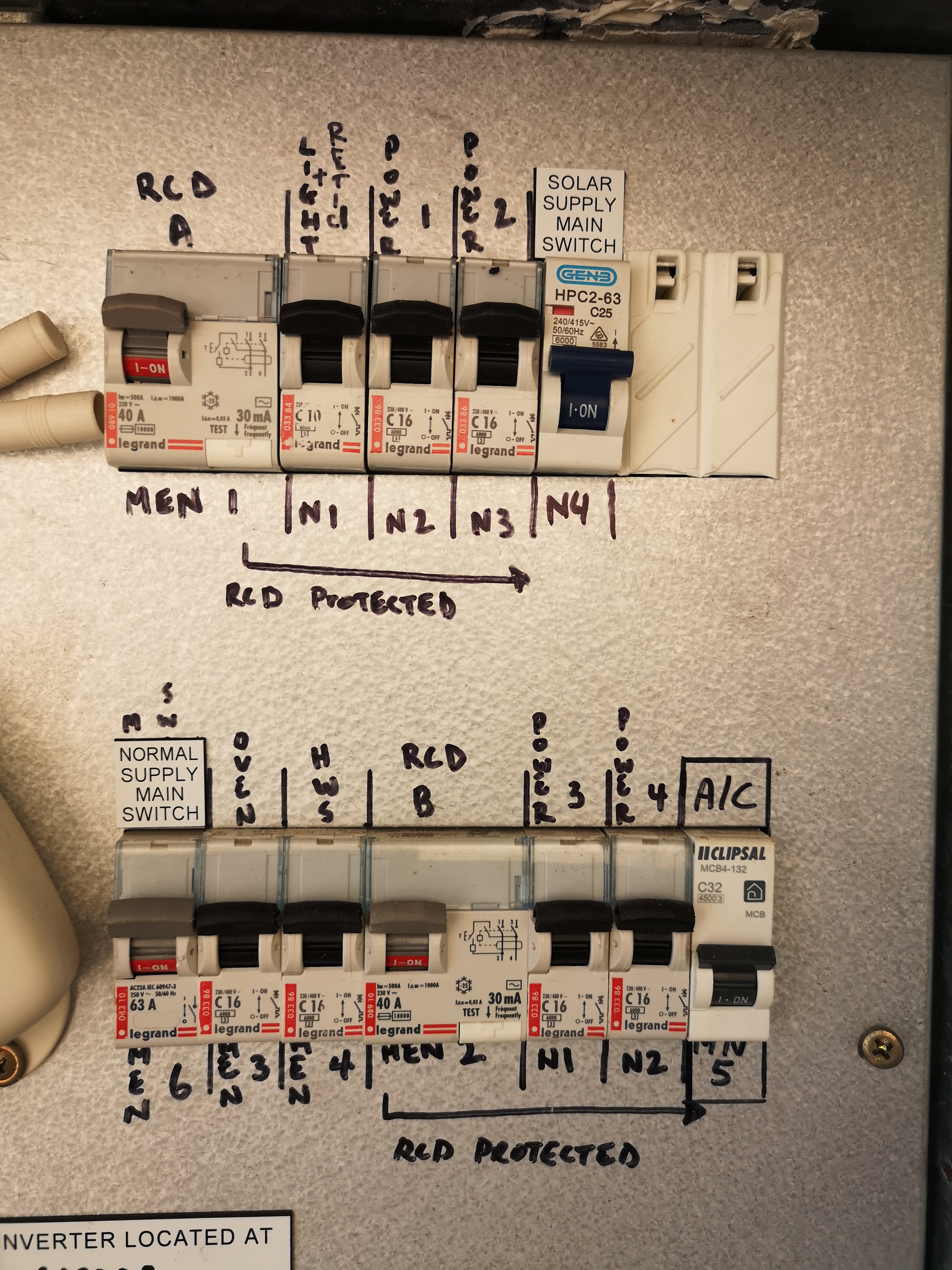
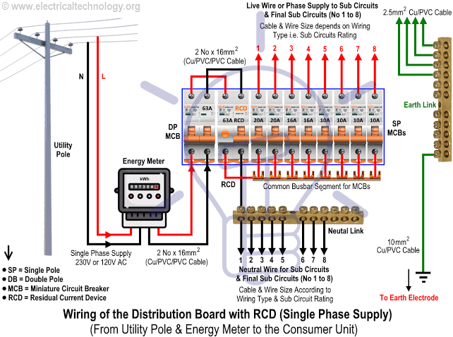
Current situation is:
RCD A (40A): 1x Lights (10A), 2x Power (16A each)
1 x Solar Supply (25A)
1x Oven (16A)
RCD B (40A) : 2x Power (16A each)
1x A/C (32A)
Main Switch (63A)
I’d like to monitor Solar (already getting this data off Fronius wifi but may as well get another source), A/C and pretty much everything else can go into one bucket. Can they be hooked up off the RCD’s?
I have a double outdoor power point just outside of the meter box that currently powers my retic. I am hoping to use this to power my iotawatt. I’m hoping a sparky can put a hole on the side of the meterbox (Bottom has a gas meter so not an option), with some ducting and glands etc. to a separate enclosure that will house my iotawatt. The CT’s will be run via the duct into the meterbox.
So i’m hoping to find an enclosure big enough to encase the outdoor powerpoint and AC adapter, as i’m guessing I can’t just plug the AC adapter into the powerpoint and expose it to the elements? or is this a non issue?
Would be good to see other people’s set ups so that I can make sure I have all the products ready for the sparky to do the install.
Residual current device, detects earth leaks and trips to reduce accidental shocks and faults etc. It is a requirement in aus that circuits be protected by rcds.
Learn something new every day. In the USA we call it a GFI (Ground Fault Interrupter) or one of several variations on that theme.
You have a single-phase system, so it is not necessary to measure the neutral. In fact, the RCD pretty much guarantees that the neutral will be exactly the same as the L conductor.
So 1x100A for the main as you say plus
1x50A for the AC
1x50A for the oven
1x50A for the solar
That leaves six circuits. You can setup an output to compute the total of those circuits as “one bucket”.
If you put one CT on each RCD, you can get the total of the remaining circuits on each RCD as well as the HWS.
If you add six CTs to each of the remaining circuits, you get the usage of each circuit.
Perfect, so just to clarify, it can be configured to show
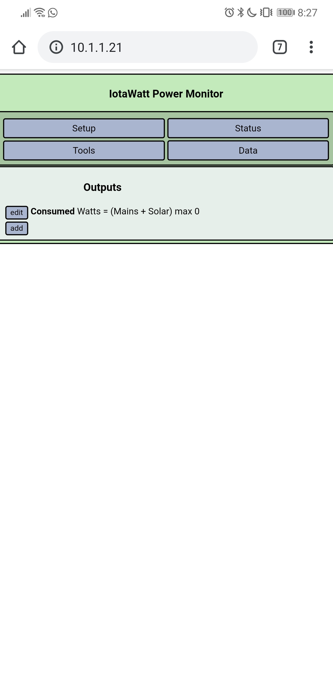
Mains minus AC minus Oven plus solar as the other bucket?
With regards to the solar, we use the power that we create, but then also sell back excess to the grid. How can I monitor how much I’ve used vs sold back? Will that just be an instantaneous calc for power created minus usage?
Depends on the tariff. If you have true net metering, then the answer is yes. If you meter import and export separately with different rates for each, then you would need to upload the data to PVoutput, influxDB or Emoncms to integrate the import and export numbers. PVoutput allows setting tariff parameters to get $$.
By example, here is a link to daily PVoutput data with import and export graphically and in the table below.
costs us ~37c per unit to buy from the grid, whilst we only get ~7c for what we sell back. Which is why it’s quite important to see if we are producing excess or not, to decide when we use our high power equipment such as Washing, Dishwasher etc.
Already using PVOutput for the solar generation, but will investigate influxDB to better integrate with Home Assistant.
Thanks again for your help Placing an order shortly.
Hey Hobo, I’m in Aus as well.
I also have single phase with solar and use the little 50amp solid core CT’s on all my monitored circuits.
For the main active (from the meter to the mains switch) I use a 100amp split core.
I chose the 50amp solid CT’s (3) for their compact size and sturdiness ( no hinge or clip to break ) and I figured they would be more accurate as they would be operating within their midpoint. All my sub circuits (power) are 20 amp, so the 50A Ct could handle a “double” circuit if needed. The only issue with these is the need to physically put the cable thru the CT. (disconnect/reconnect wire from breaker, so might need a sparky)
I chose the 100amp split CT(1) because I have a 80amp supply and it is easy to fit over the main incomer.
I initially started with monitoring the “mains(incomer)” , “solar” , "power’ and “lights”
I discovered that I would like to monitor more closely, so I purchased another 10 of the 50amp solid CT’s. which I will install with my meter box upgrade.
The only real “quirk” I discovered was with the 9volt reference. As it is AC, it needs to be wired “in-phase” with what the CT’s are reading. No biggy, you might just need to change the “polarity” of the VT so that everything makes sense.
Besides that, easy to install and setup. An excellent piece of kit.
Thanks for the message. I placed an order yesterday, went with the 1x100A CT for the mains, and then 50A CT’s for the A/C, Oven, Solar and ordered two spares. The HWS shown has been decomissioned so should be consuming 0. I probably should switch it off, though the powerpoint feeding the HWS is still in-situ.
Would be good to have a forum section for install pics!
Take a look at the “Case Studies” section as this has a good mix of people’s install pics, etc. May be what you are looking for. I find it fascinating how there are so many different type of power installs around the world. Enjoy looking at the many different panels and connections.
I have to do some cable management, and then i’ll share some pictures etc. but I do have a few queries
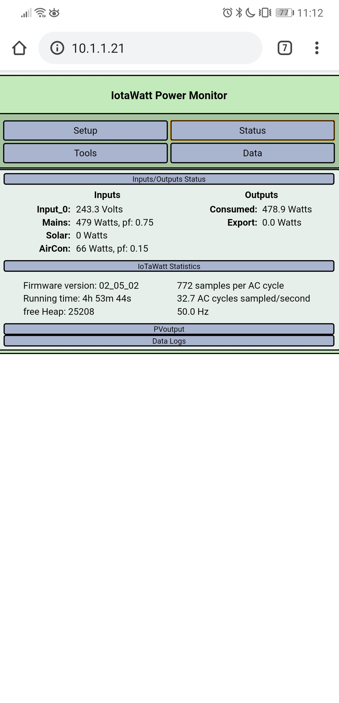
I purchased the AcuCT-H040-50 and AcuCT-H063-100, but neither of these are options on the iotawatt setup. Any suggestions which one to select? For the time being, I have selected ECS16-100 and ECS10-50 and the results seem to be somewhat what I should be expecting.
The air con is showing as 199W on standby – this could be a result of the wrong CT being selected, or a fault in the air con? Not sure. Google seems to have lots of people having the same issue using clamp meters on different systems (not iotawatt). Any thoughts/Suggestions?
Looking forward to playing around with this more over the coming few days
Photo of the CT will be difficult as need the electrician to come back. I did watch him install it and it was on the cable out from theCB for the air con only.
But interestingly it has now dropped to 65W…Still more than I’d hope but at least in the realms of reality.
It is winter here so speedy is probably right… Will monitor it more tomorrow.
Any suggestions on the CT type to select in the model for settings?
Is it a heat pump (reversible) or just an AC? If just an AC, maybe you should think about switching it off. In any event, what does happen when you turn off the breaker, does it go to zero?
Did you get them from the stuff shop and if so what was the order number?
One last thing. You seem to be using the “Original Graph” to view data. That is deprecated and will soon be removed. The other choice Graph+ is much more useful and provides access to much additional metrics.
Based on what you ordered, the 100A CT is AcuCT-H063-100 and the 50A CTs are AcuCT-H040-50.
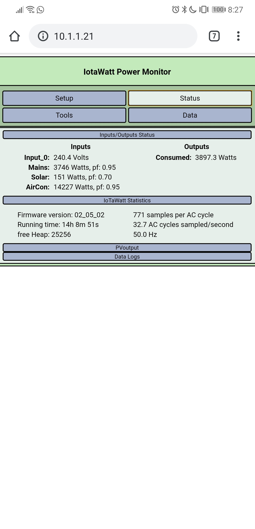
Taking another look at the Aircon load, the power-factor is .15, so that is probably not a heater. Can you show the status display with the AC running and if you can, post a picture or state the nameplate rating of the unit. Is it an integrated unit with air-handler? If the CT model was was wrong, it could be overstating the power.
for 16 kw unit, that ““residual consumption”” around 200 watt can be the heater for compressor; this kind of compressor need to be heated in order to be able to run at any time for the purpose scope, special for heating time. in the another hand, to heat the compressor can be done in two ways: one way is with a pure resistive element that is around the case or compressor and second way is with a coil inside compressor that is power supply for the inverter used for normal way of working of the compressor unit. anyway, this not explain the power factor that is in the picture attached by initiator of this post.
once more, this explanation is valid only if all condition of install of CT are OK and configuration on IOTAWAT are OK.
Thanks for the replies, I’ll post a more comprehensive reply shortly. Its raining and miserable today here in Perth Australia.
The CT models you have mentioned are not available on my dropdown menu. There’s definitely something weird going on as my air con value is more than the mains. The solar is negligible due to the weather.
I’ve clearly made a mistake on the outputs side, but I followed the instructions on the iotawatt - pvoutput set up page.
 Placing an order shortly.