First, my IotaWatt is fantastic and properly AC referenced numbers are spot-on. Very happy with this product 
I put a standard IotaWatt purchased 50a CT on an incoming generator 120v source. It has a 5ft extension to reach the IotaWatt unit. Since I can’t do a 4th AC reference, I’m using an unrelated live AC reference (I1Vref in pic below). This was my recent 4th AC reference query - Adding a 4th AC Reference - OK to use plug #12? - #2 by overeasy
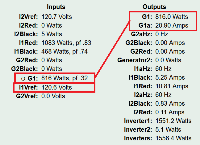
The generator is putting out ~20a @ 120v = ~2400w as verified by the charge going into my solar system battery but IotaWatt is only reporting ~800w (instead of 2400w) which I assume is related to the .32 pf
Here’s a snap to show Inputs/Outputs…
Curious as to what’s happening. Why would pf be so ‘off’ / why only 800w instead of the actual 2400w. The amps (20.9) shown above are reasonably correct. Can I compensate somehow to get a closer wattage number?
This is not a critical measurement but it would be nice to be within 10% +/- if possible.
You need a voltage reference from the generator to get accurate Watts and PF. Amps should be nearly correct though.
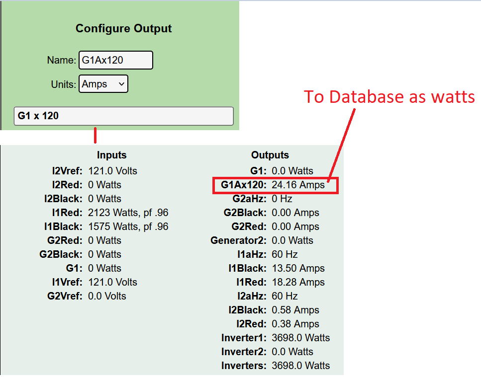
Sounds like I could do amps * 120v (hardwire the 120 in the output rule) since I’m sure the generator is doing ~120v and use that as my watts.
I thought about that but the way outputs work is that you can’t mix units, so the output would be expressed in Amps even though you know its a Watts approximation. Probably doesn’t matter if you are uploading it somewhere but it might be confusing looking at Graph+, and your WH would be Amp-Hours as well.
What are you using the three voltage inputs for? Maybe there is a better alternative for one of those.
I see what you mean about ‘mixing units’; however, this is OK for my local monitoring and I appreciate the suggestion. The quality of info - e.g. amps * 120v (fixed number) is close enough for my purposes and I can live with the ‘residual’ amps * 120 noise that’s causing the ‘24.16’ pseudo watts reading as show in this pic. Looks like noise is 20-80 range which is only 1% to 4% of 2000w actual which is perfectly OK for my purposes.
I use IotaWatt to monitor/gather-data on my off-grid solar system. I have 2 x battery → inverters that produce AC to home circuits and I have 2 x generators → chargers → battery that feed AC to chargers. These are 4 independent pieces of equipment. A 120v reference is used for each of the inverters to monitor power output. The 3rd reference is for generator #2 to monitor AC input to a charger. And now I’m trying to monitor a 2nd generator - and thus the 4th AC reference.
I thought about manually moving one of the AC references back and forth but I’d rather have fuzzy / weirdly labeled data for 1 of the generators and be able to run all 4 units simultaneously.
I notice that I1Vref and I2Vref are the same. Is that just a coincidence or do they synchronize and both feed the same panel? When inverters are connected to a grid fed panel, they produce power in phase with the grid. Unless you have two independent electrical services, that may well be the case and you can use a single voltage reference for the two inverter outputs.
Yes, thank you for noticing / trying to help!
I1Vref (Inverter1) and I2Vref (Inverter2) are used to monitor AC → distribution panels for each individual inverter. In winter (lower PV), for greater DC->AC efficiency, only 1 inverter is active and the Inverter #1 distribution panel is cross-fed to the 2nd inverter’s distribution box - so I1Vref and I2Vref are the same AC. These distribution boxes feed AC to home circuits via ATSs downstream of these distribution boxes. There’s no grid-tie as the ATSs keep grid AC → home separate from inverter AC → home. In higher PV times of the year (May-Oct) both inverters are active to be able consume the greater PV and the 2 x VRefs are needed.
The generator distribution box is for the larger 240/120v split-phase generator #2. That leaves the smaller, Generator #1 AC input at 120v only off to the left of the pic that has been unmonitored till now.
Maybe someday I’ll find a single 24,000w inverter at a good price, and that would free up a vRef. Alternately, it’s not worth a 2nd IotaWatt just for this 120v generator AC when I can get an aproximate incoming wattage number.
It is possible to modify the IoTaWatt to accept additional VT inputs. there was a method used by three-phase folks with the old V4 IoTaWatt that had only one VT input. I didn’t endorse that method because it involved drawing 50mA from the VT and thus producing 1/2 Watt of heat.
Looking at your picture with what appears to be DIY battery packs, you may be able to handle changing the internal burden resistor on the input that you want to use for voltage from 20 Ohm to 1K Ohm. If you did that and added an external 12K Ohm resistor in series with the VT, you could treat the input like the other three VT inputs.
The internal burden is an 0805 SMT resistor right next to the 3.5mm input jack.
If you would like me to change the burden, you can send the IoTaWatt to me. It would take me a couple of minutes and I can make a pigtail to go from 5.5mm (VT) to 3.5mm (CT input) with a 12K resistor inline. I can do it for twenty bucks and return postage.
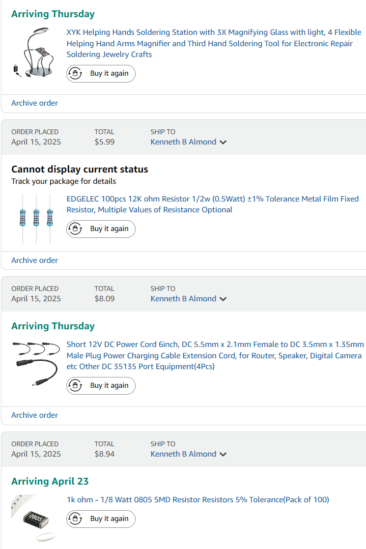
Thank you for this info and thank you for the incredible offer to do the mod. It so happens I bought a ‘backup IotaWatt’ that I haven’t used and I think I’ll give this a go myself on the backup unit. I have the fine-tip soldering iron but ordered a helping hand / magnifying glass ‘unit’ and maybe that will help me succeed
Looks like these are the parts I need…
And this is an example of the burden resistor to swap out to 1K…
Couple of things:
The cord has a male 3.5mm DC plug which is a barrel jack. You need a 3.5mm headphone jack.
The burden that you have marked is input 14 which cannot be used because you are already using it for a VT. both 13 and 14 are dual purpose but can cannot be used for VT and CT the same time. The switches inside the jacks are wired to switch over when one of them, but not both, are in use. You can use any of the remaining inputs 1-12.
You should calibrate the VT after setup. IoTaWatt uses 0.1% resistors for that circuit. Once calibrated though, its all the same. I’d recommend you calibrate with the VT plugged into either the grid or a good inverter output before using it for a generator.
1 Like
If I’m understanding, I need to put a 12K resister in series with the DC 9v + and - and then hook the + and - to the headphone jack to plug this into input #12 (for example) where I’ve swapped out the 20 Ohm with a 1K Ohm.
Here’s a stereo headphone extender of the type I just used to extend an IotaWatt CT recently. Can you advise the hookup from the AC reference DC 9v + and - to the stereo headphone wires (yellow, white, red)?
OK, I was able to solder in a 1K Ohm to replace the 20 Ohm on input #12. A little messy but I think it’s solidly soldered…
A jig with magnifying glass was absolutely needed for me - the resistor is sooo tiny. I used a small soldering iron you see in the pic. This is my back up unit and after I’ve verified it works, I’ll apply the same upgrade to my main unit.
@overeasy was sooo gracious as to fix me up with a 3.5mm / barrel jack connector with 12K resistor.
Will give all this a try in a few weeks when I have some time and report back.
1 Like
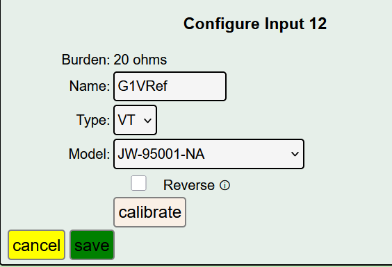
Things appear to be working! Here’s my Input #12 VT setting after changing out the resistor.
**I’m ignoring the default 20 ohm burden setting as the other vRefs also have 20 ohm as their defaults.
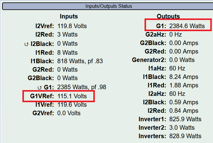
And on the Status screen I have Generator #1 (G1VRef) showing 115.1v on a Honda eu7000is 120v plug.
and reasonably correct G1 Output wattage as I know the battery charger settings and battery state.
More Detail: The battery charger is set at 40a and is ~90% efficient (+/- 2%) from past experiments. Thus 2384.6 * .90 = 2,146w / 55.0v (current battery voltage) = 39.0amps of charge going into the battery. The 1a difference (55w) between this calculation of 39a actual vs charger setting for 40a is on the money considering the fuzziness of the charger efficiency/settings. This is certainly accurate enough for my purposes.
Fantastic!
1 Like