I’m interested in installing iotawatt in my home in Massachusetts. I am comfortable with software and programming, and like that iotawatt will allow me to log data from multiple circuits into open source databases for analysis. I’m not comfortable with electric wiring, and could really use expert advice on what to buy and how to get it installed safely.
My goals are to
Track power consumption time series of a multi-zone Heat Pump system I am considering installing, and correlating it to data from temperature sensors, to make sure the system is operating efficiently
Tracking power generating from my solar panels (I already have generation monitoring from the installer, but it’s logged in their proprietary platforms and extracting the time granular time series data is manual and time consuming)
Tracking power consumption of my electrical vehicle charger
General monitoring of other consumption to identify efficiency opportunities.
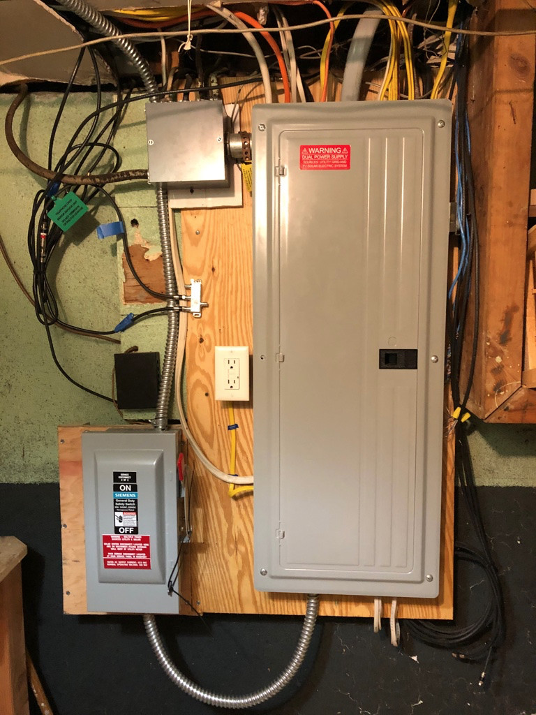
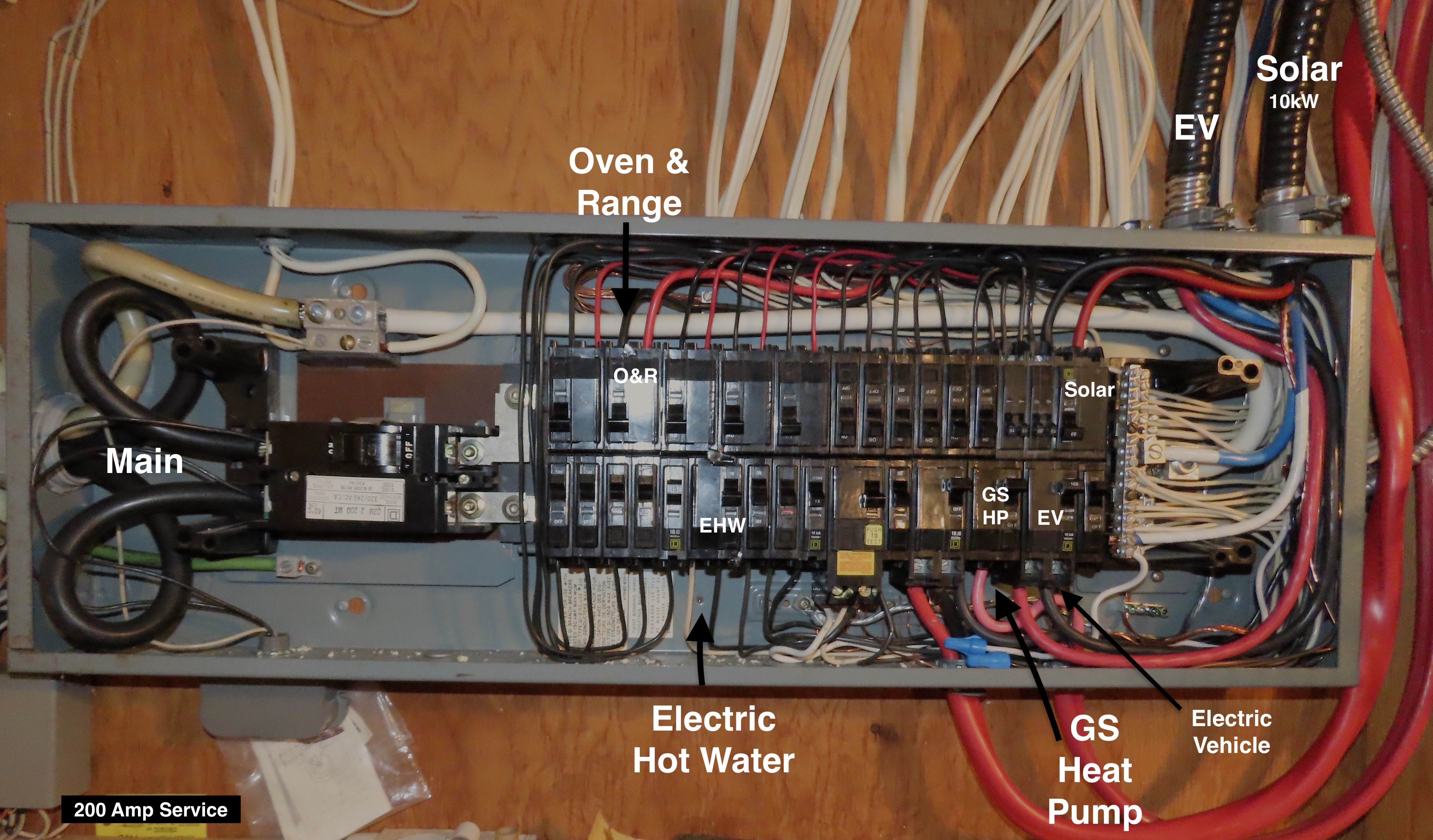
We have 200A service and only one electric panel currently. If and when the heat pump system is installed, we will likely add a 100A sub-panel. I have attached pictures of my panel. I don’t have a photo of it with the cover removed because I do not feel qualified to remove it myself safely.
Is there anything I need to learn or other information I need to provide to choose the right iotawatt hardware and have it installed safely? I’m willing to put work into this but not sure where to begin!
Safe to say that an IoTaWatt North American bundle with 2x 200A CTs for the mains is the starting point and one 50A CT for your solar. That will measure whole house consumption as well as solar generation and net usage.
Without specific information about the branch circuits you want to measure, it’s not possible to offer more than general advice. You will need one CT for each 120V circuit and 240V two-wire circuit (no neutral). You will need two CTs for each 240V three-wire circuit or one CT if installed as described in the documentation. Circuits with breakers greater than 50A will need 100A CTs.
You can connect a total of 14 CTs (includes the mains).
I recommend having an electrician or someone comfortable with working inside an electric panel review your requirements and install the equipment.
I noted that the AccuCT 50A x 10mm split-core is for “Solar Inverters to 12kW”. My array is 12.48kw capacity, but I have never seen it generate above 10kw. Can this CT be installed and used safely?
PV arrays are usually expressed in terms of the DC output of the collectors. If you have 30x270W collectors, that’s would be an 8kW system. Depending on orientation and local insolation, you will typically see less AC generation than the DC capacity. If you have never seen more than 10kW, that may be the capacity of your inverter. You would see maximum output on a bright, but cool day - usually early June in northern areas.
In any event, 10kW is quite a bit below 12kW, so good to go with the 50A CT.
Safety is a “funny”/special/lawyer-involved word. When you use that, you are generally asking that can I do this an sue you if something bad happens. This is why you see so many safety warning labels on products. But, as Bob pointed out, there is a simple solution, get the 100A CT. The 100A CT is physically bigger. Some might argue it will not be as accurate at lower currents. They might be right, but does it really matter for your use case? What decisions are you going to make with the data?
I regularly look at readings from my 50A CTs to see 1W differences in usage. Are they real? Does the CT have enough linearity and repeatability for the readings to be trusted? (Unclear, since those are not spec’ed.) But, for my usage I can tell that the old system I had controlling the heater in my goat yard used about 3W more power than the new system.
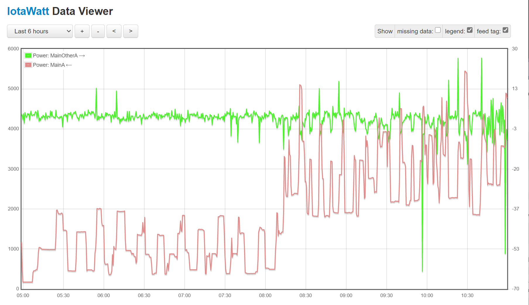
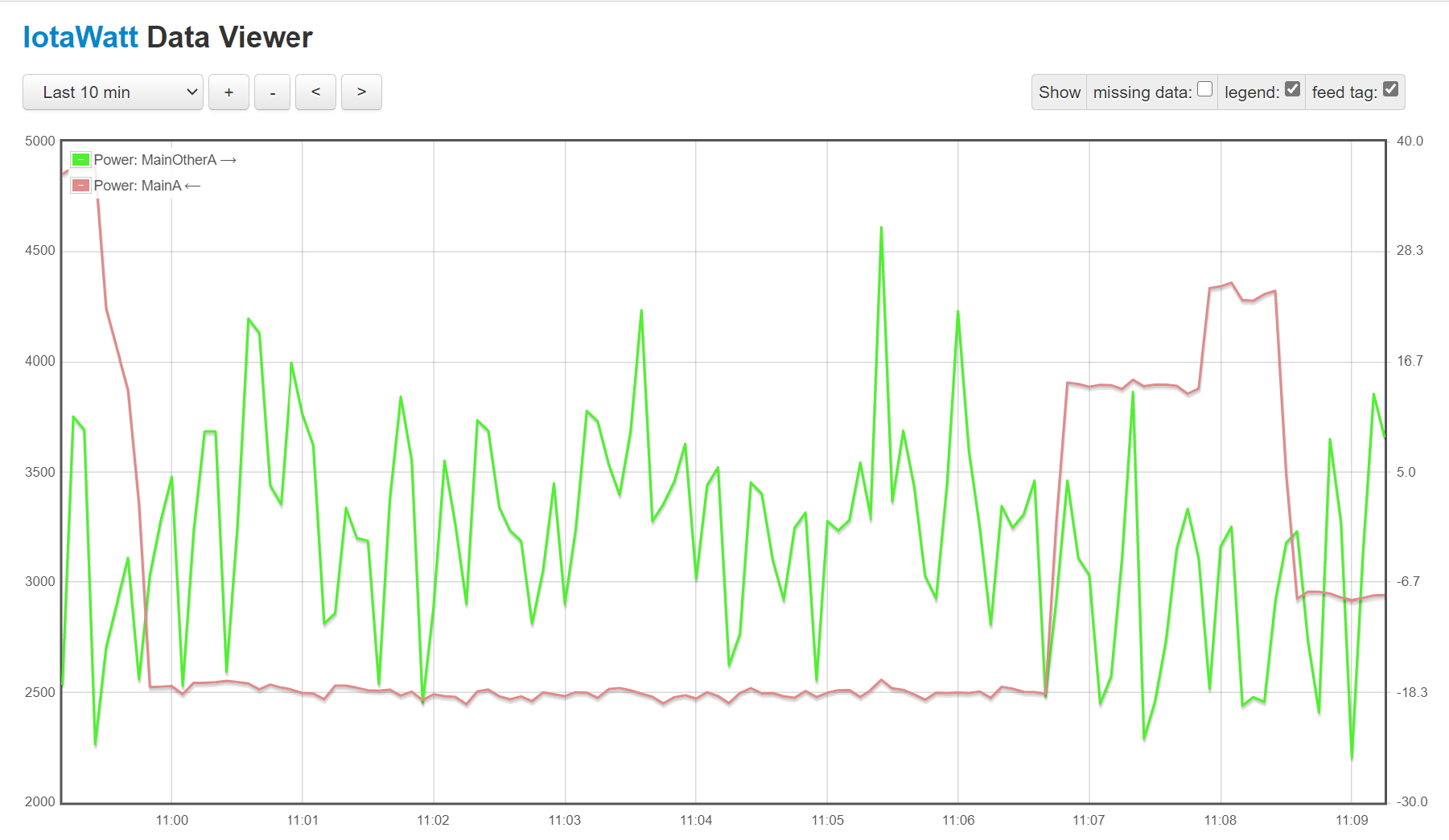
So, it is safe to use a larger capacity CT on a smaller line. It will also give you very good results. I have been running two CTs on the same line. One is a 200A one and the other is a 100A one. Here is a graph of the difference between them
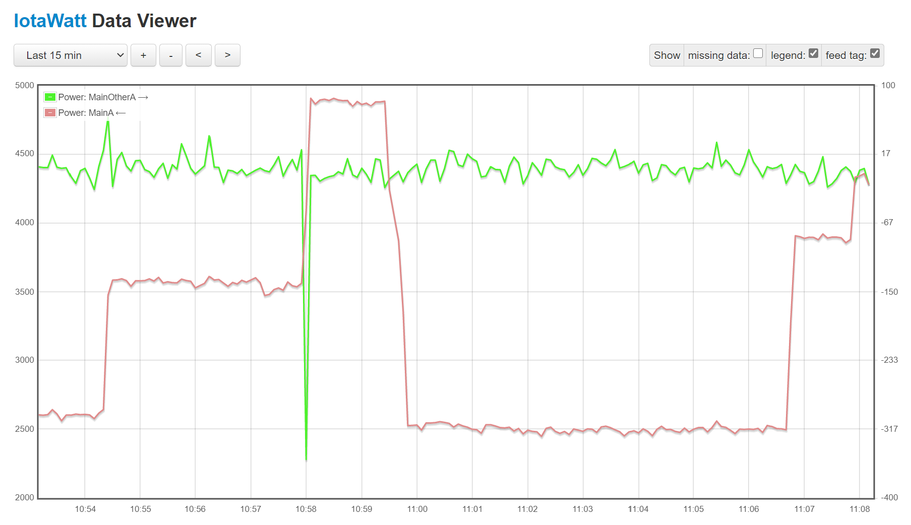
Most of the time both CTs measure the same wattage (within a few W). But, you will also see that there are a few spikes, where the numbers differ by a significant amount. If you look closely, you will notice that they occur at points where the actual power being used is changing significantly. This is likely due to the fact that IotaWatt does not sample all channels continuously. So, during a change in power utilization, one channel will read the old value and the other will read the new value.
Here we can see that most of the time the numbers agree to +/-15W. The load is about 2500W. 1% of that is 25W. So +/- 1% is +/- 25W, I am seeing better than that, so I consider that good enough.
Thanks to both of you! I’m not trying to ask lawyer-y questions, just asking dumb questions out of pure ignorance. Feels like my next step should be to find an electrician who is comfortable helping with the install.
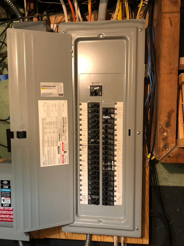
Looking at the pictures, you have a large service entrance panel with standard 1" size breakers and 200A main service. It looks like there is one empty spot for a breaker, so you will probably need a sub-panel to have enough spaces. You will probably need to move at least one circuit over to the sub-panel to free up space for the double breaker needed for the sub-panel.
The main entrance cable appears to be the big gray one that is probably 4/0 for the main conductors. It looks like there is lots of room, so CT placement should be easy enough. But, yes, you will need someone to open the panel and take a look around to see how to wire things up.
Since you already have 39 + 2 circuits/breakers, you will need to make some choices about what you really want to see. It is really easy to say EVERYTHING. But, think about what you are really going to do with all that data. I first started down this rabbit hole/journey having just the instantaneous usage value for the whole house. That was interesting but really hard to visualize and turn into information to make inferences to make decisions. Many years ago, I got a system that had 2 channels for the mains and 5 additional ones. That helped, but load disaggregation turns out to be a really hard problem. I did gain some information and did make some decisions (I bought a Heat Pump Water Heater). Several years ago, I bought my first IotaWatt. With 14 channels, I had more data, but still it wasn’t enough. So, I bought a second one. With two, I could actually measure the voltage on each leg to see just how different they really are. But, this meant I had to use 2 channels for each of my 2 water heaters and 2 main pumps, so I combined them in ways that would let me tell which was running. But, the two pumps look very similar and don’t run for long, so hard to see in the data. I had been thinking about getting 2 more IotaWatts, but I decided to actually look at the data and do the math to see if I REALLY cared about the inaccuracy from assuming both legs have the same voltage. I am reasonably convinced that I don’t really care that much and I would rather know when things are running. So using the same 4 channels, I can get independent data on my big loads.
Since you probably don’t know what you are going to do with the data, I would start with a single IotaWatt. On my first system, I got lots of “extra” CTs to allow me to try looking at different circuits to see which ones are really interesting.
The variation in voltage between the legs, caused by unbalanced 120V loads and resistance in the neutral conductor, is something that keeps coming around. I took a hard look at this quite awhile ago, so it’s time to revisit that:
I did take my own advice and have my production IoTaWatt setup with the 230V Euro transformer connected to my 240V. I scale down the calibration to 120V (actually calibrated to half the 240 voltage). When doubled for the 240V loads, it’s always exactly right. More than half of my usage is from 240V appliances. The total of the error for the 120V legs is also reduced significantly.
New here and not sure about the etiquette of asking the same question for my “about to make” purchase. I am in Ontario Canada and have a 10 kw net meter solar setup (32 panels with 8 APSystems micro inverters). I want to monitor the PV in, the mains (200 Amp service) and a few circuits.
Solar in
Electric hot water
Ground Source Heat Pump
Electric Vehicle
Suggestions on an equipment would be appreciated.
Thanks
Mains 2x200A clamps
HW 1x50A
Solar in 2x50A (appears to have neutral?)
GSHP 1x50A (Can’t read breaker value, if it’s more than 50 use 1x100A)
EV 2x100 (Appears to have neutral?)
Don’t know what the fat red cable next to the GSHP is, but it appears to be a two wire circuit so probably 1x100A CT if it’s something you want to measure.
Can’t read the over/range breaker value. If it’s 50A or less 2x50A else 2x100A, although the usage for that appliance rarely amounts to much in the overall picture.
From the wire gauge, the rest should be OK with 50A CTs. The 240V circuits would require 2x if three wire (has a neutral).
Bob Thanks for the quick response. I didn’t want to hijack ahasa’s thread.
Solar is 3 wire: Red Black Blue (neutral) partially Taped in white to indicate.
EV is the same: Red Black Blue (neutral) partially Taped in white to indicate. EV breaker feed a sub panel which has a 50A breaker for the EV Charger and a 20A breaker for a 120 plug.
So good there
Mains…Good 2x200A clamps
HW…Good 1x50A clamp
GSHP: not sure as the breaker is not labelled. If I go with 2x100 is that OK or should I call the electrician that installed the unit to get the real amperage?
The fat red cable next to the GSHP is the auxiliary backup plenum heater. Used only once since 1996. Not worth monitoring. I’ll not bother with the oven/range either.
My main concern is; Will the CT’s fit in my full panel box? Any concerns here?
My interest is to monitor PV in and Net with grid as well as GSHP, HW and EV.
I will share my PV data as well.
So just before I place my order:
Looks like this will do it.
At the risk of overcomplication, If your EV subpanel has a double pole breaker for the EV charger and no neutral going to the actual charger, then you can use a single 100A on a hot lead and a 50A CT on the neutral. With that, you would be able to differentiate between the EV load and the plug load.
Looks like you have plenty of room, with the exception of the GSHP CT which will be a squeeze.
I may be adding a 15A circuit or two out there in the future. I’ll have a look tomorrow to see how the EV charger is wired. Then I’ll place the order at IoTaWatt Stuff.
Thanks for the help
db
Just checked the sub-panel and the feed to the EV charger does have a neutral.