I’m wondering if what I see is “real” reactive power and some way how the PW works…
Yes, there are two sets of “visible” CTs, one for solar and one for mains. One on each phase for a total of 4CTs.
I installed the IoTaWatt CTs alongside these for those two feeds.
For the power wall, I installed an extra pair of CT’s, they measure the current internal to the transfer switch or the power wall…
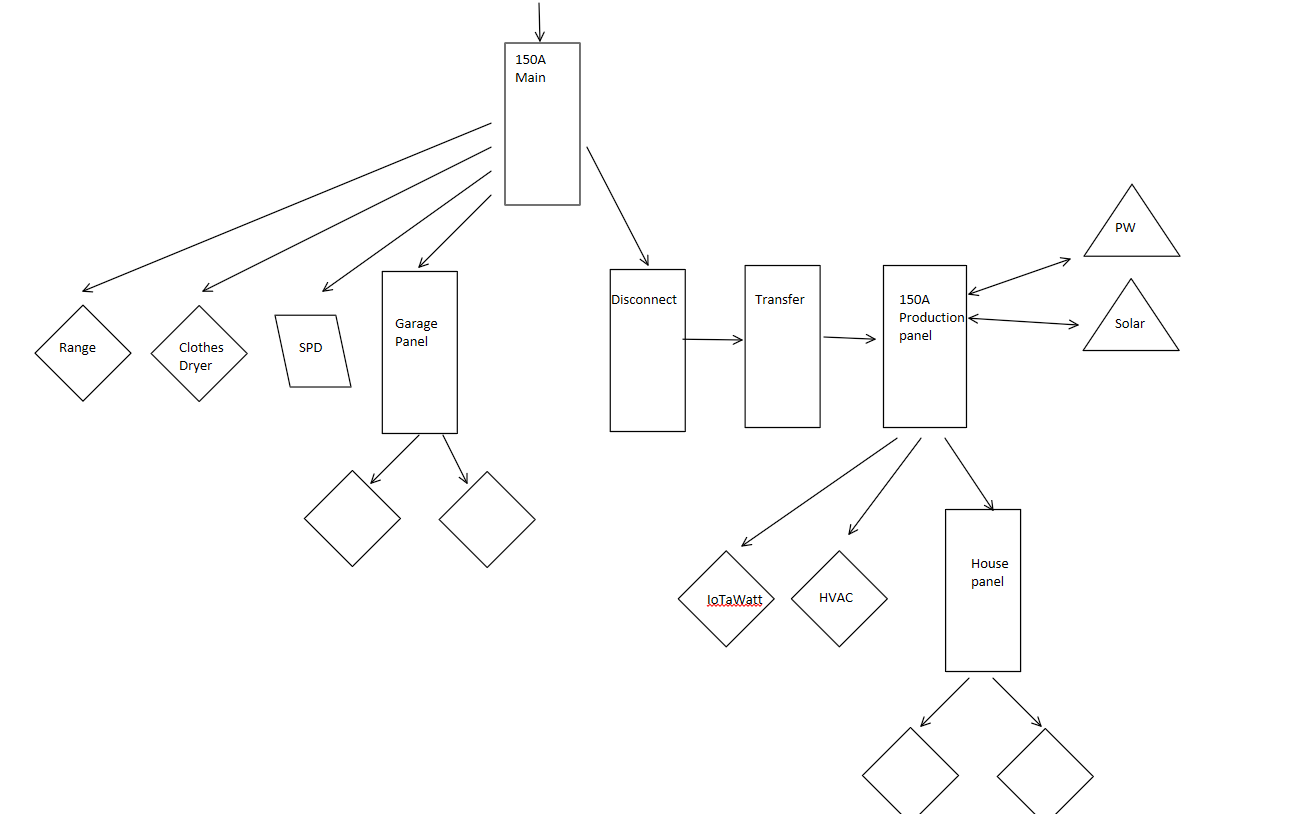
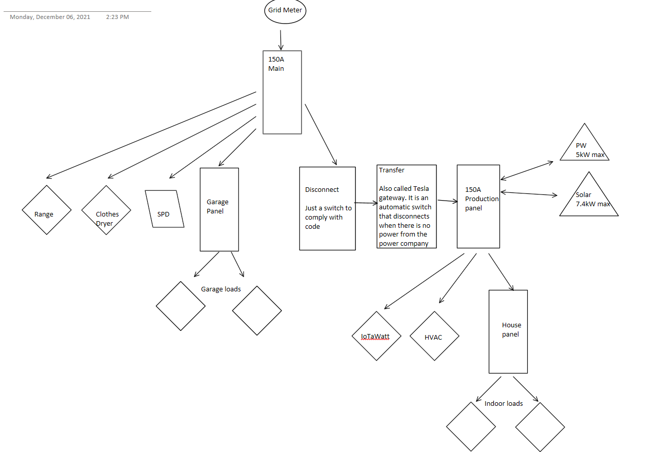
The transfer switch (see modified diagram below) will detect a loss of voltage and disconnect the utility side from the Solar and the Power wall isolating the grid for self-generation.
I do not have a generator, the Transfer switch (rather an automatic disconnect sorry for the misnomer) will
just open up when the grid looses power.
In my diagram below, I get a 150A breaker feed from the meter to my main distribution panel. On there, I measure with the CTs (as well as the power wall). (Note: all loads I will describe here are 220V loads. On the first two panels, all loads are 220V)
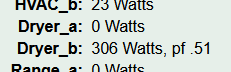
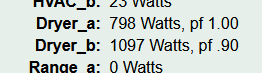
In that same panel, I have 2 loads that are also measured by IoTaWatt: The Range and the Clothes Dryer. I have another feeder to a sub-panel in the garage but I will eventually add another IoTaWatt there to measure the incoming current to that panel and the individual circuits.
From that panel, I have a straight through connection (after the 150A main breaker there are lugs that go yout with no further breaker) into a simple manual disconnect switch, required by code.
From the switch, I go to Tesla’s Transfer (rather called Tesla’s gateway) switch, again, an automatic disconnect. Tesla’s CTs go into that circuit board and I presume they also get voltage measurement there to know when the Grid lost poser and open the switch (rather to know when it comes back).
From Tesla’s Gateway I go to my generation panel. I get 7.4kW on 220V from the solar inverter. And the power wall can deliver/consume 5kW, also connects in that panel. I monitor both loads with CTs. That gives me a total of 10CTs.
From that panel, I get a 220V for IoTaWatt (more of that later) and a feeder to my house sub-panel that are not monitored with IoTaWatt. Again, as soon as I get my two recently ordered IoTaWatts I will add monitoring to the house panel Feeder (total of all circuits) and individual circuits.
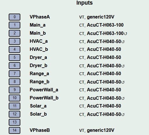
So as you can see I am measuring every line in a 220V fashion (both sides of the split phase)
I have 220V to the IoTaWatt because I am using two TRIAD transformers (120 to around 10V) to measure each side of the split phase. I did this just because I can…  I did a field calibration with a TrueRMS DMM with 0.08 + 0.03 accuracy spec for 200V@60Hz
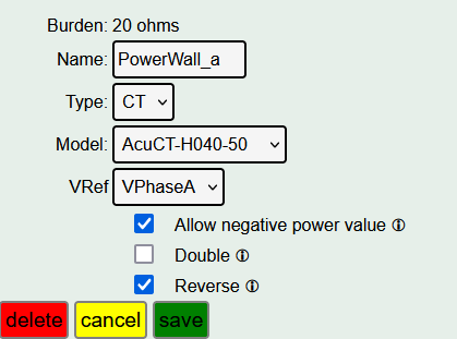
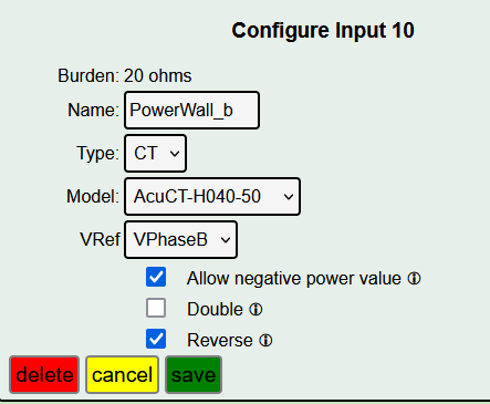
So each CT on phase A is referred to VphaseA and same with CTs on phase B with VphaseB
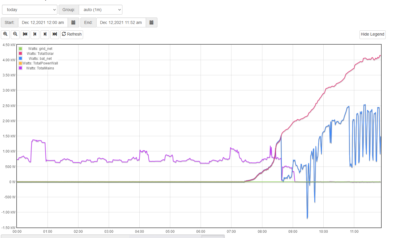
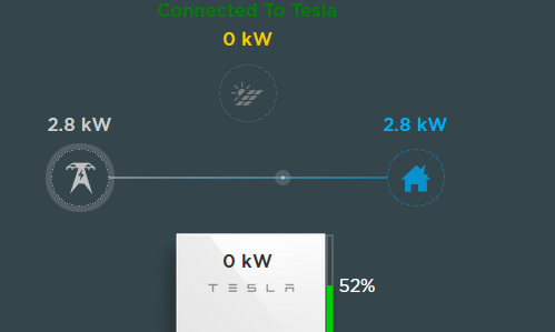
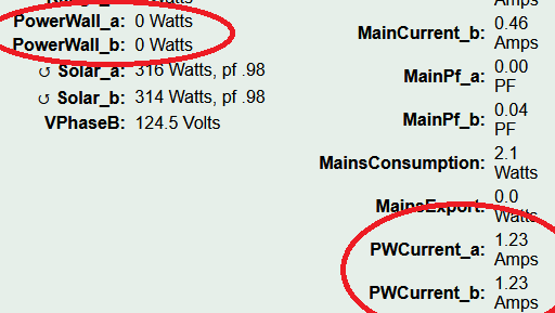
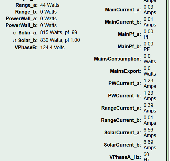
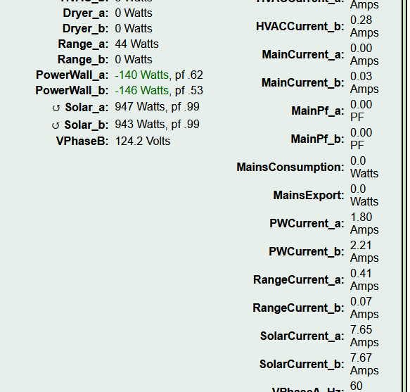
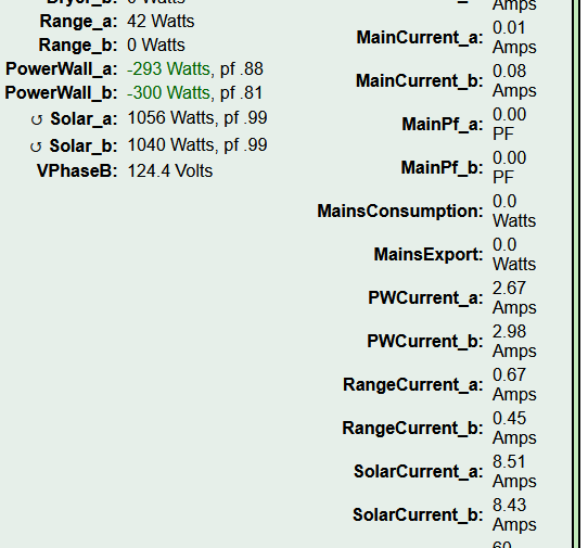
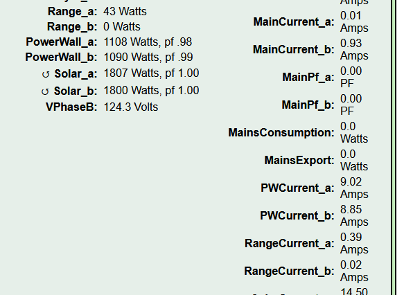
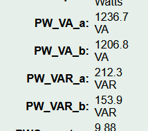
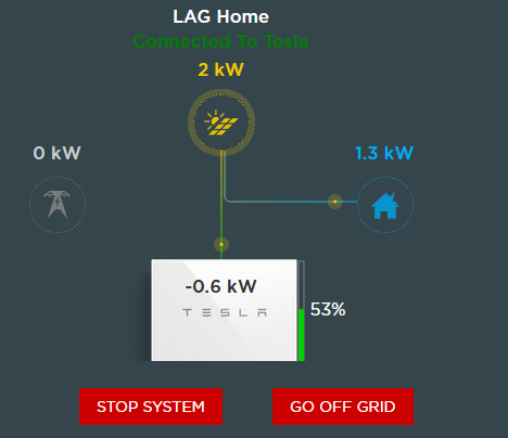
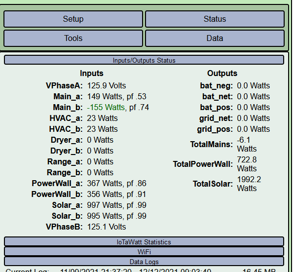
Now that my Power Wall is fully charged, I get this:
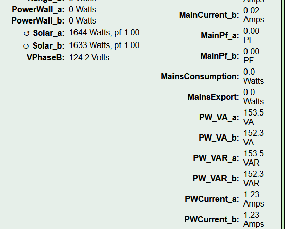
Note that the current is the same in both channels, and VA and VAR are the same… with the Power being at 0…
Still trying to find if this is a behavior of the Power Wall or what…
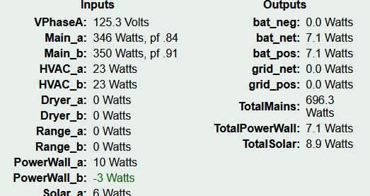
Also, I tried swapping channels and the issue traveled with the Power Wall…


 .
.