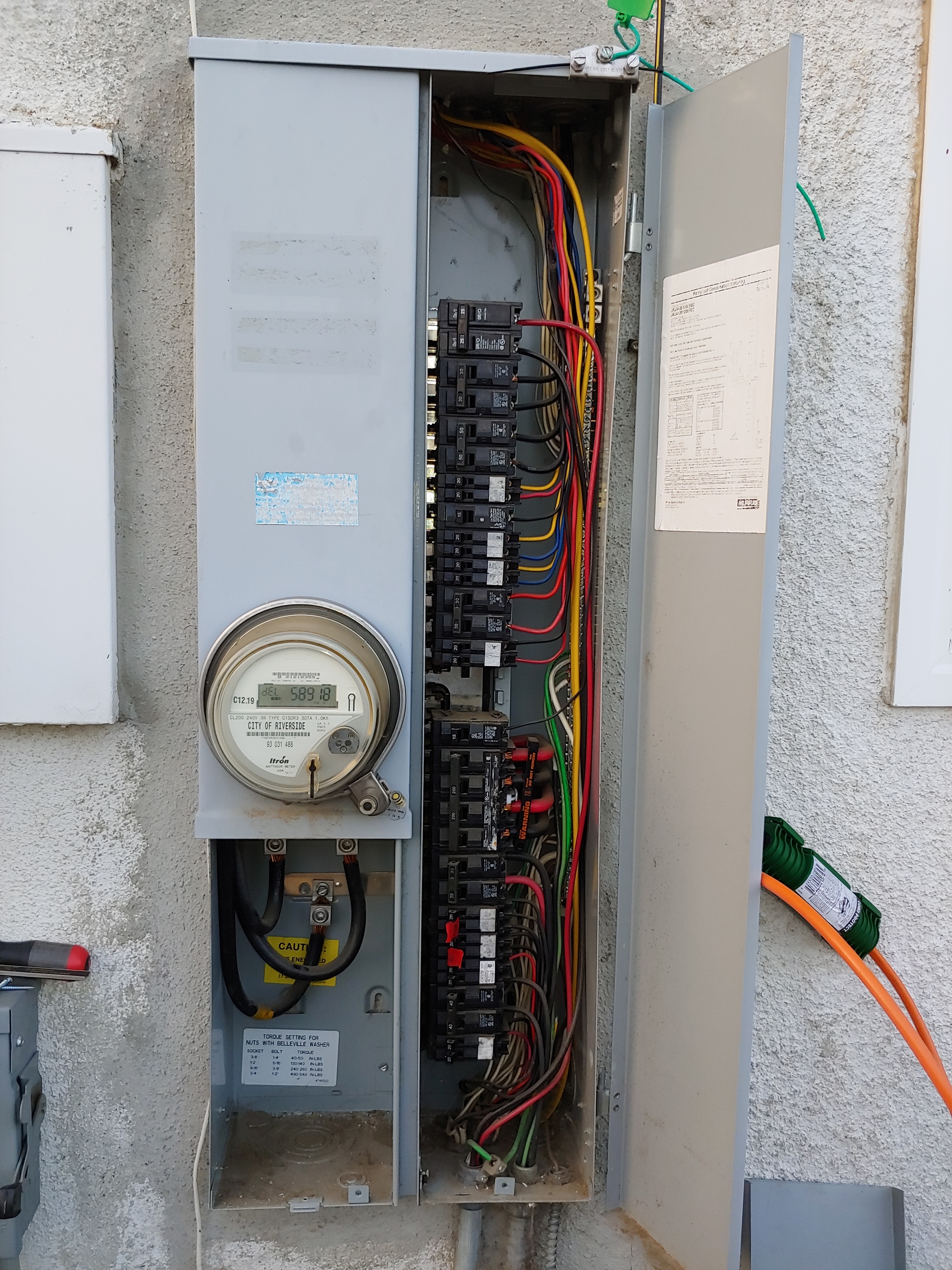
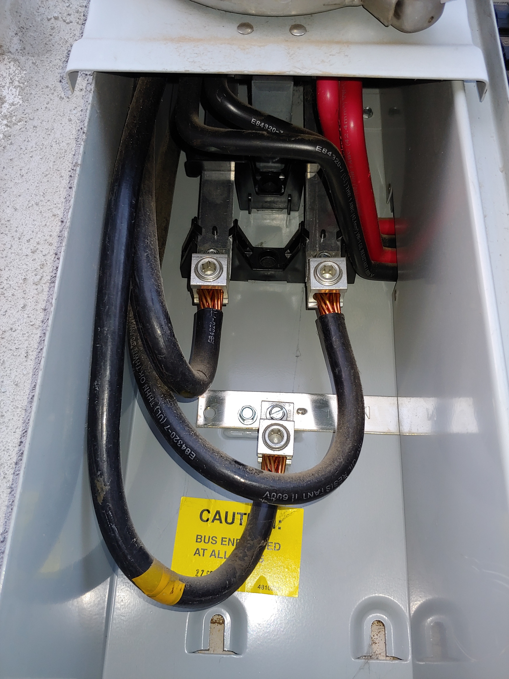
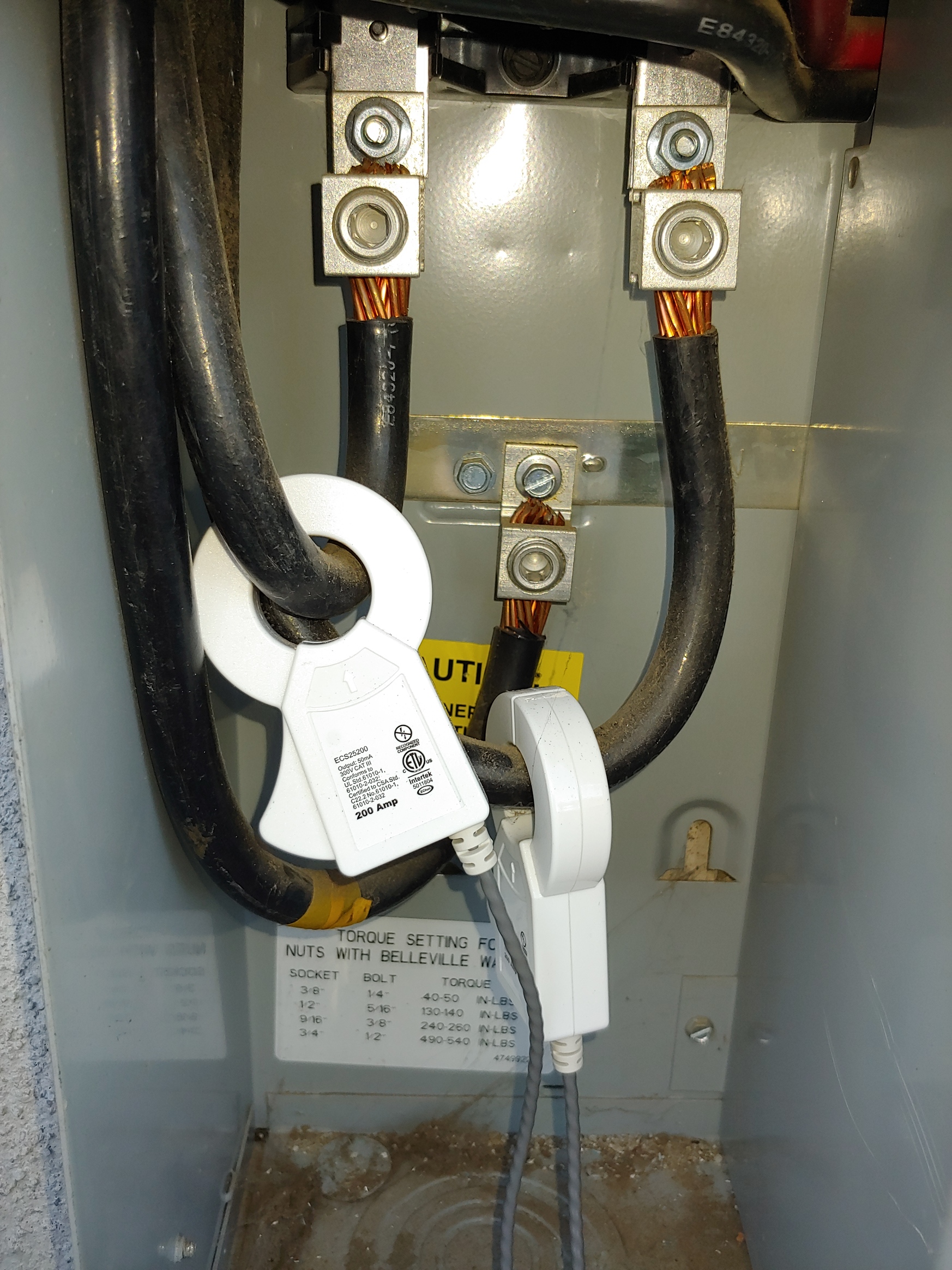
The first challenge, as in the other post, are the mains. Here’s a pic looking up into the meter at the lines in from the city and the four mains out to the panel:
2 CTs on the lines in from the city. There will some loss through the meter but it will be minimal?
4 CTs on the 2 black and 2 red mains. Probably no enough room to fit 4.
2 CTs on the 2 black and 2 red mains. I would need at least 30mm openings in the CTs.
The 400A CTs with 36mm openings are currently out of stock. Are there other CTs, perhaps from other suppliers, I could look at for option #3?
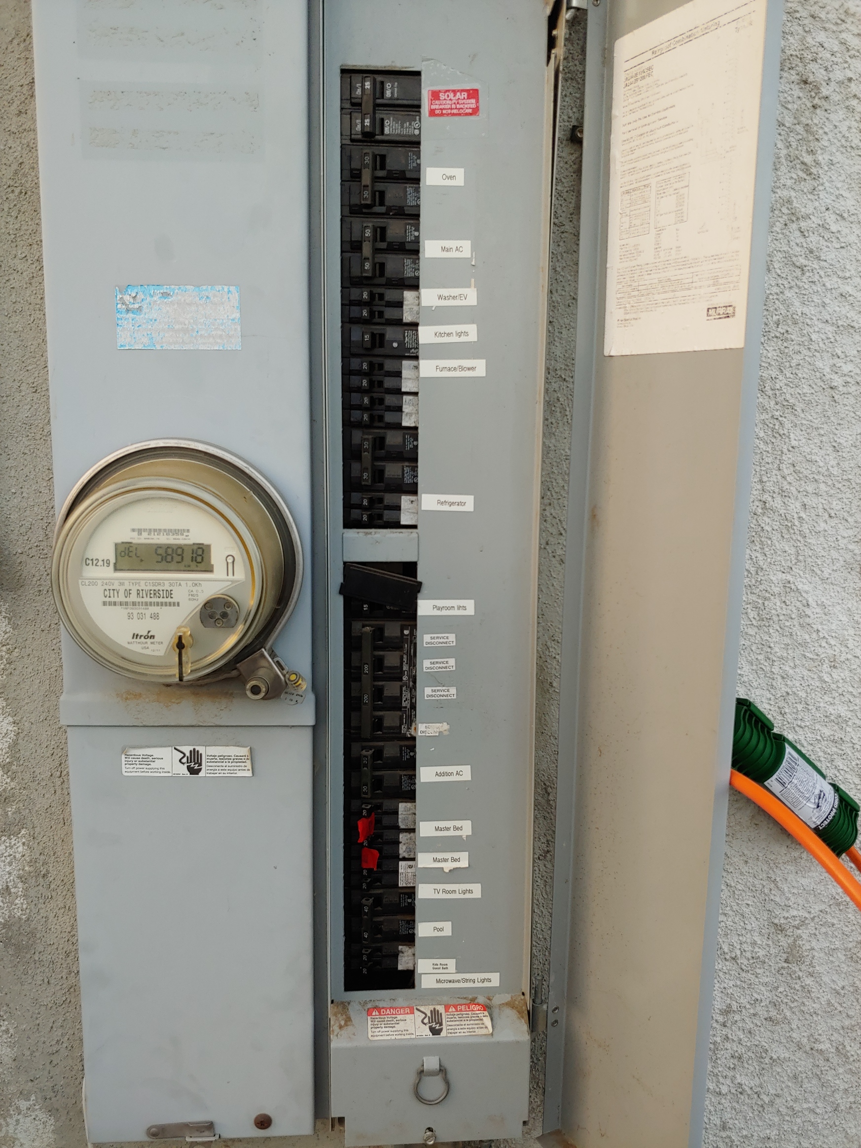
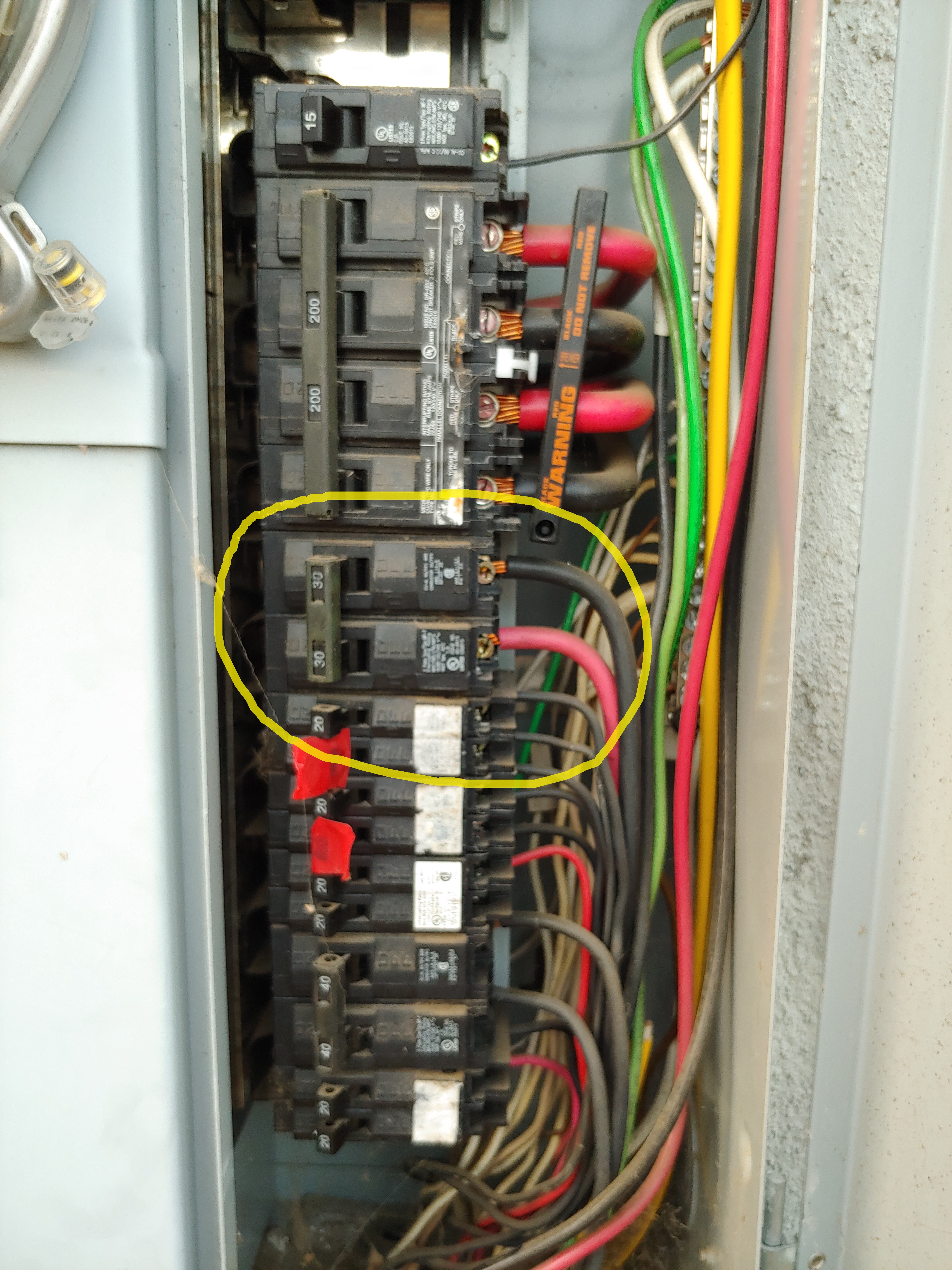
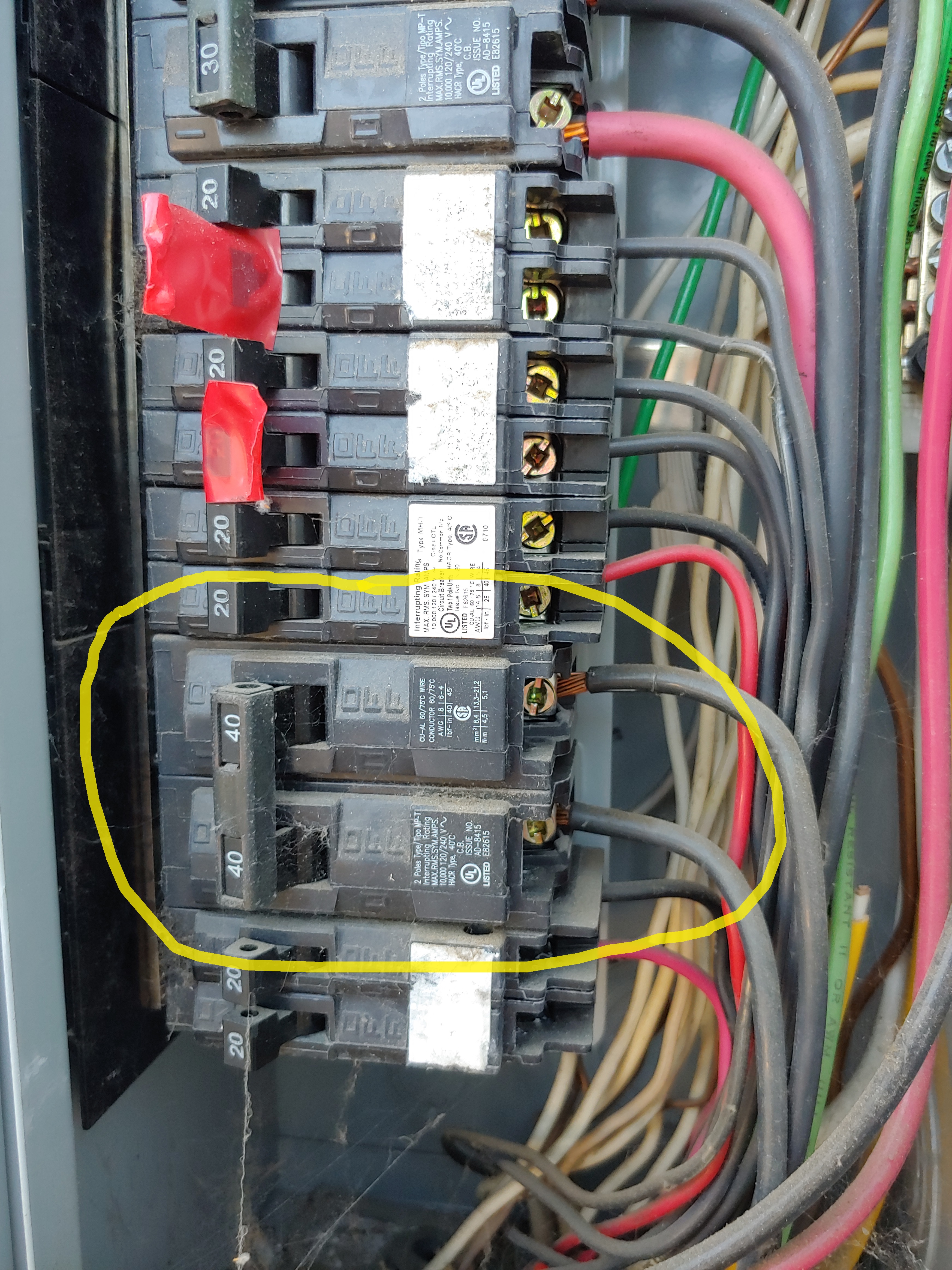
My other 2 questions are about breakers. The first is a breaker to the AC in the master bedroom addition. It has one red and one black, circled in yellow:
Normally in this situation I think I could use 1 CT and double the value. But in this case since there are 2 different sources do I need to use 2 CTs?
The second question is kinda the inverse. I have a subpanel near the pool for the pool pump and sweep. At the main panel 2 40a black wires go the subpanel, one to the pool pump and the other to the sweep:
From what I’ve read in the forums, normally when you have a subpanel you want to read both wires from the main panel. But in this case since both wires are black and I’m only interested in monitoring the pump, can I just put a CT on the wire to the pump-side of the sub panel?
Sorry if some of these questions are obvious. I’m a noob learning as I go. Thanks for the help!
In the thread that you referenced, the lower left cover was sealed. Since you appear to be able to remove it you can just install 200A CTs on the two mains from the street. There is no loss through the meter.
In general, 240V circuits require 2 CTs or passing both wires through one CT if there is a neutral wire. 50A should be fine.
The bedroom AC is probably two-wire, but you need to verify. If it plugs in, then look at the plug. Does it have three or four prongs? (one is ground).
The picture of the pool sub-panel shows that the circuit is three-wire. The neutral is a black conductor wrapped with some white tape. There are 120V circuits in the panel, a sure tipoff. So the subpanel requires that both lines be monitored. Monitoring just the “pump-side” is not an option as it appears to be 240V (as expected) and uses both sides.
Many thanks, Overeasy. This is a big help. The bedroom AC is a roof-mounted unit (common here in SoCal) and I can’t easily access it. I’ll plan to use 2 CTs on that. For the pool subpanel I’ll run both black wires through 1 CT. The only thing I regularly use on the subpanel anyway is the pool pump.
The other somewhat tricky bit is that the panel is semi-recessed and all the access holes on the right side are used. I’ll have to go in through the left bottom, drill a hole into the right side and then run the CTs. I’m working with an electrician and will post some pics of the install.
It’s a big relief that the mains aren’t complicated, as I feared.
Hey bkgeig, I was the one who posted the original thread you referenced. I wound up having the CTs installed on the 2 mains from the street in the lower left corner. There is just not enough room anywhere else in the panel to get CTs on mains. Technically reading the power consumed by the meter as well, but it’s so small compared to the use of the house that it’s negligible.
Thanks for the reminder on reversing the CT; I probably would have forgotten.
Nice to hear from you, brgr. Wasn’t sure whether you were watching posts. I hope to get mine installed in the next couple of weeks. Had to move some poorly installed coax cables this morning. Now I can fully open the panel to access the breakers.
To be clear, it’s one of the conductors that must be passed through the CT in the reverse direction. Looking at the pictures, that may be very difficult unless there is some slack in one of them. See this in the documentation.
Yes, my plan was to splice in a short piece of wire to give enough slack to reverse the direction. I’ll probably use solid-core CTs since space is tight.
For the solar feed at the top of the panel, is it still OK to use one CT and double the value?
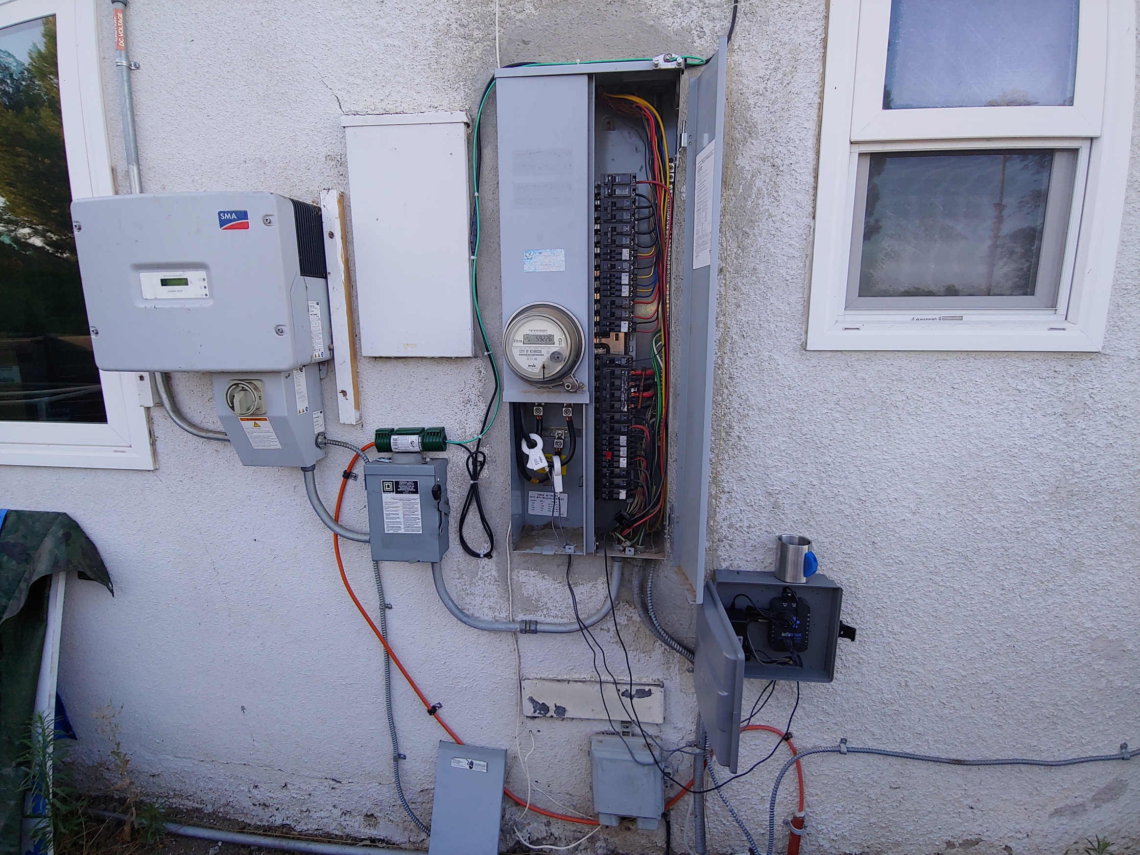
Got the initial install done over the weekend. There wasn’t a great place for the waterproof box. Ideally I would have put it to the left of the panel, but the solar inverter is in the way. I thought about mounting it below the panel on 2x4s so that it was on top of the electrical pipe, but that didn’t get me much closer to the breakers. In its current location I’ll have to use 3.5mm extenders on some of the top breakers. I ordered some 1m extenders from ebay.
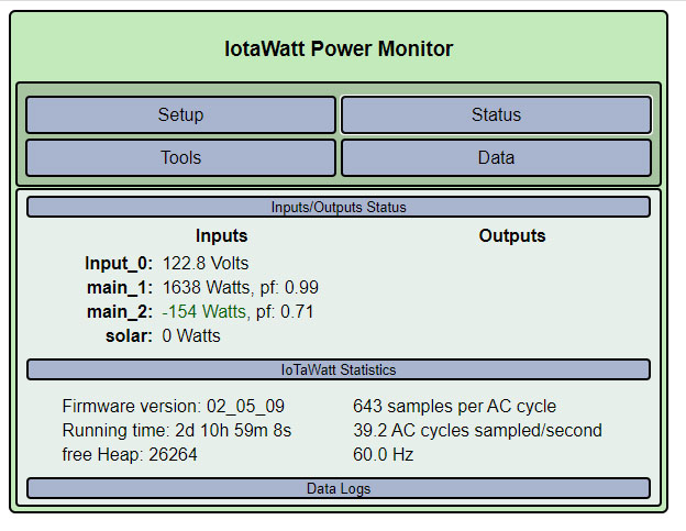
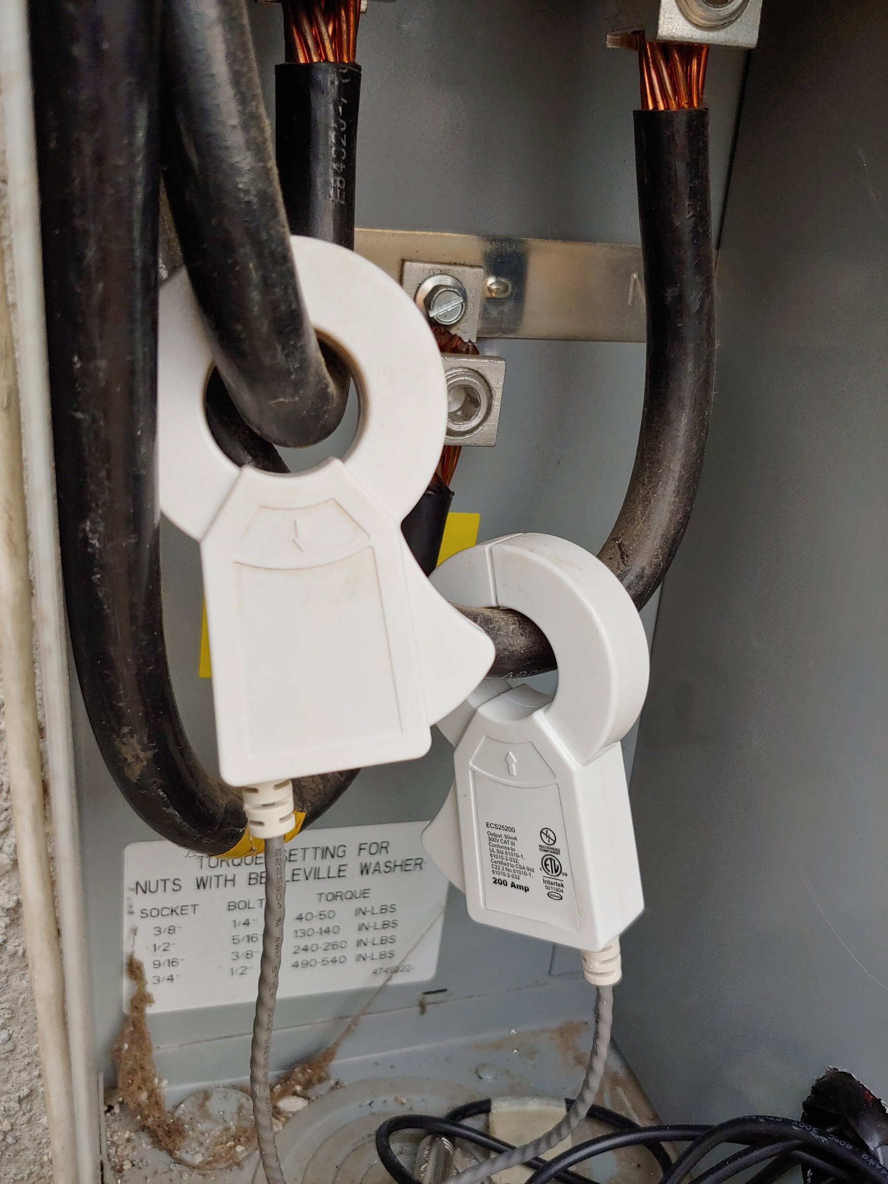
Something doesn’t look right about the mains, though. I’m showing a negative input on main_2 even when solar is at zero. I checked and the orientation is correct (it’s the left CT in the pic). Is this normal?
Looking at the picture, they are oriented the same way. One should be reversed, or the reverse box checked in the configuration. That should explain the negative value, but 154 watts seems to be low when the other is 1638. Those clamp type CTs are shipped with little squares of treated paper between the faces of the iron cores to protect against chipping and corrosion. They usually just fall out during installation, but sometimes the inner one stays and causes these kinds of errors. Try opening them up and blowing out any paper that’s still in there.
There was paper in one of them. Very easy to see too. Not sure how I missed that on installation. main_2 is now physically reversed on the wire. The outputs look more balanced: 215 and 534 with 0 solar.
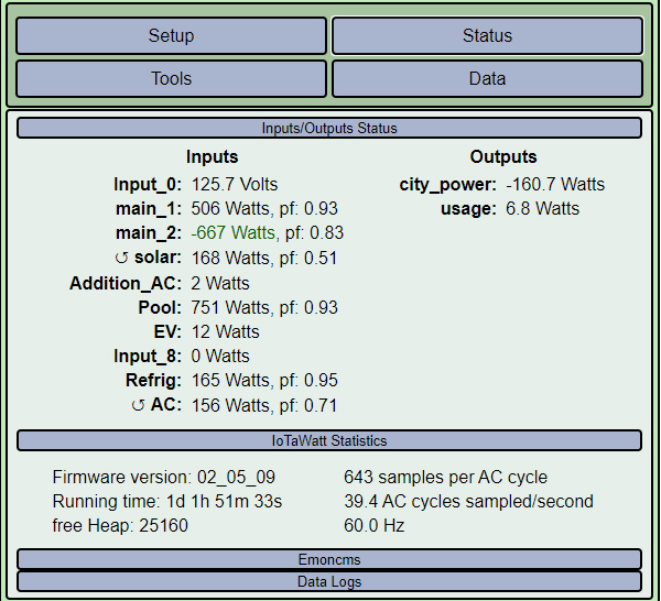
Got most of the CTs installed this weekend. I’m still not confident about the main readings; they seem wonky to me. This morning at about 7:30 solar had just started generating but main_2 showed -667 watts. The mains are physically reversed on the wires.
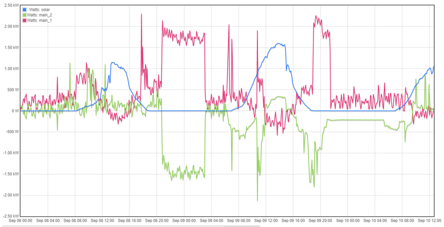
Is this what you’re looking for? Looks fascinating to me, but I’m not sure how to interpret it. This goes from 12am Tues to now. FWIW, the spikes around 9pm correspond to the EV (not charted). We have not been running the ACs this week.
OK, sorry, this was total user error. The CTs were physically reversed but I had also “reversed” main_1 in the setup. I thought I had triple-checked everything. Now the CTs are reversed and the setup left normal.
I have same Siemens panel, new as I just installed Solar. The mains coming in, L1 and L2 have foor wires, like the picture other post shows.
I cannot get into that part of the panel as it is locked by the energy company.
Even if I could, and I have sat, any power sent back to grid would be measured, which i do not want.
As the mains within this panel is so tight, any options with using Rogowski coils instead of CTs?
Rogowski coil options would be great for tight spaces, but I see no options for Iotawatt (or others on market for home use, but in higher end solutions (corporate/commercial).
Don’t really understand what you mean by this. If you measure the mains and your solar production exceeds your usage, the mains go negative. If you don’t want that, you don’t want to measure your mains, end of problem.
Negative. Not sure you could get one in there anyway. The mains alternate phases so one leg is 1,3 and the other is 2,4. You would need to join the weaver’s union.
As previously outlined, the easiest and most straightforward way is to get inside that lower left compartment and install a couple of 200A CTs. There’s tons of room in there.
Otherwise, there only other option with this panel is to measure everything else and add it all up in the IoTaWatt. Not as hard as it sounds if you combine some of the circuits into one CT. See the docs on that.