I have this 200A Siemens meter/panel combo installed on my house. I just got PV installed and am interested in tracking consumption, starting at the mains level and then eventually expanding to a circuit level.
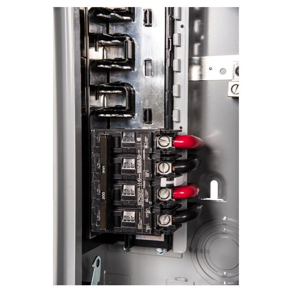
This panel features a built in meter/mains connection with a 200A breaker. The issue is that it has 4 split-phase wires (2 per split-phase) that are a large gauge and not at all flexible.
My question is - what CT configuration would be best for this panel? I’m 99% sure I need 4 CTs just for the mains sensing, but should I combine each phase with a splitter as has been mentioned elsewhere? And what size CT would be appropriate for each wire? I would think 100A, but maybe I need 200A per wire? That seems a bit excessive.
That is going to be really challenging. There is no room to get most CT around any of the main wires. If the main wires were a little longer, you could probably fit a smaller CT. You might need able to fit a 100A CT on each of the mains. I would combine the two reds and the two black wires’ CTs.
For the mains, I don’t see any way out of pulling the meter. That usually involves an electrician and a phone call to the utility. The electrician pulls the meter, installs the CTs, reinstalls the meter, and then the utility comes by to reseal it. If you get an electrician with a fancy truck from a big company, it will cost you a lot. There are reasonable small business electricians around. The closer to where you live the better.
As far as CTs for the mains, once you open that left side, you can put them around the service cables above the meter socket. ECS24200 should fit. They are 24mm (~1in) opening.
Moving on after that, I only see one 100 amp circuit. I’m guessing that’s a branch panel, so it will need 2 100A CTs. Everything else should be able to use 50A CTs.
Given how tight it is inside, and you will need an electrician anyway, you may want to use solid core CTs to save space. You can use splitters to combine them for 240 loads.
The solar can use just one 50A CT. Other 240V circuits may require 100A CTs if you intend to combine them. The capacity of each individual CT that is combined must equal or exceed the combined total. This isn’t dictated by the CTs themselves, but by the ability of IoTaWatt to handle their combined output. If you find that you need to combine two 100A, first try to find away to pass both conductors through one 100A CT. It’s more economical and also does a better job at the low end.
I recommended pulling the meter above and using 200A CTs, but I wanted to comment on this approach should someone find it applicable to their situation.
When combining CTs with a splitter, the individual CTs need to have a capacity equal to the combined total. This is because IoTaWatt can only handle 50mA input. If you combine two 100A:50mA CTs, they can produce 100mA combined and overload the IoTaWatt input.
You could still use 2 100A CTs, but would need to use two inputs and combine them by adding together with an output.
Yes, there is a lock. That’s the biggest problem, is removing the meter and reinstalling are a lot of work /hassle, and that’s something I would like to avoid.
It’s actually for a Tesla wall charger, not a sub-panel. Never draws more than say ~50A 240V due to the limitations of the car. 100A is the highest it can draw if I ever were to put multiple chargers in parallel, and just put the largest breaker in from the start.
Yes, was thinking solid cores on the 15A/20A breakers. Those can fit easily. Biggest unknown is whether I can cover everything or if I’ll need to pick and choose.
Take the air conditioning for example (double pole 40A breaker second from the top). If I cant use 1 50A for both conductors, you’re saying I would need 2x 100A, because 1x 50A:50mA needs to match to 2x 100A:50mA (50A:25mA x 2)?
The whole point of me asking is trying to figure out which CTs I need to buy such that I have everything on hand if/when an electrician installs it.
Most AC circuits are 240V only, so you only need to measure one leg/wire.
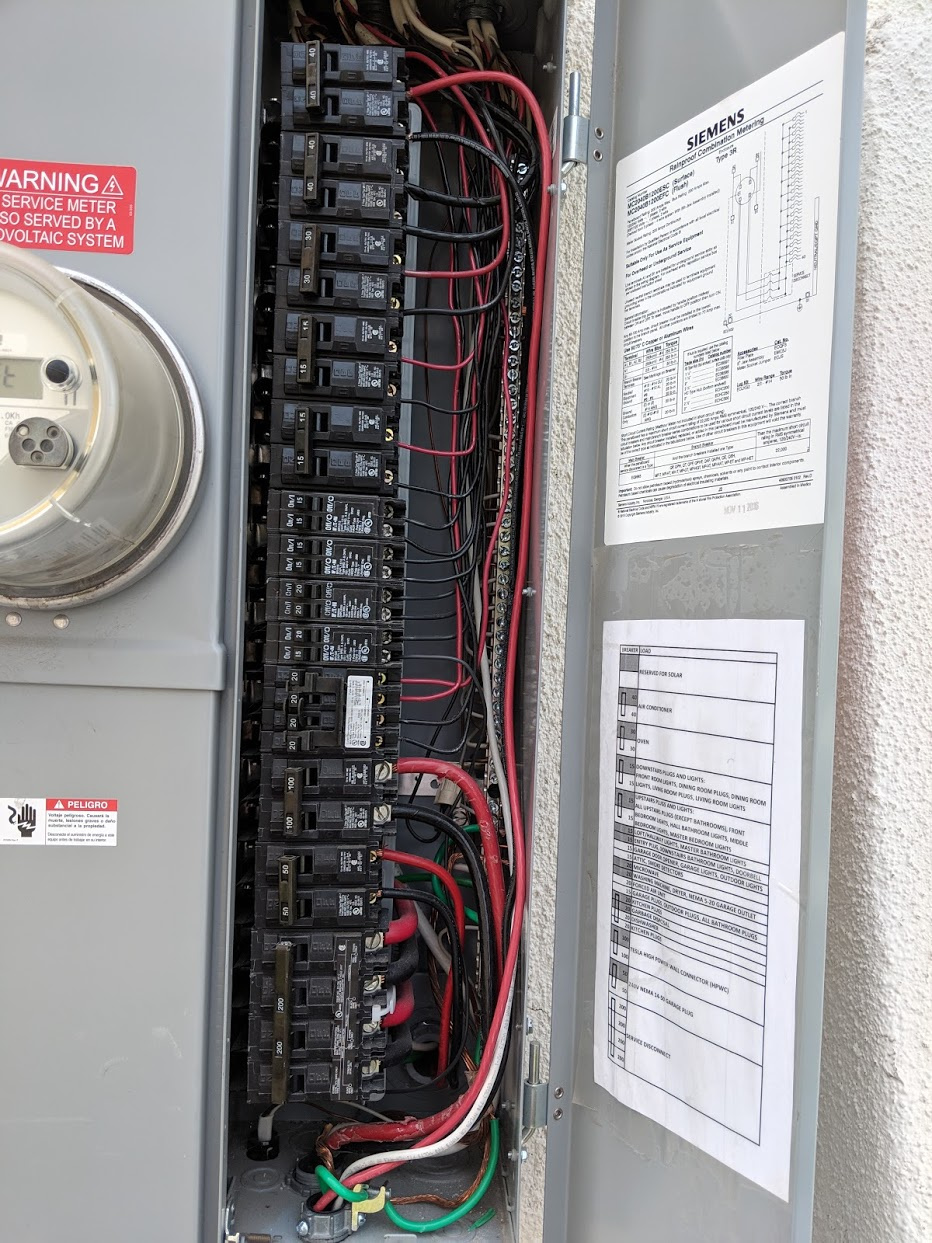
Looks like you have about 25 circuits. With two IoTaWatt devices you could cover them all and avoid the cost/hassle of opening the meter box to measure the mains.
You would have to do math on an external device/service to get the totals, but that shouldn’t be too hard.
The general rule on 240 devices is if they use three wires, that is to say if there is a red, black and a white connected to the neutral bus, then you need to measure both the red and black. If it’s only the red and black, you can just measure one and click the “Double” box to indicate 240V. You probably should use a 100A on the EV charger anyway.
That’s right. Usually an AC compressor is two wire 240V (no white neutral). If that’s the case, you can use one 50A on either the red or black and check the “Double” box. If it has a white, then you need to pass both conductors (see the docs for how to reverse one) through a single 100A CT, use two 100A CTs - one on each conductor - combined with a splitter into one input, or use two 50A CTs each plugged into it’s own input on the IoTaWatt.
Whoever wired that panel did a neat job and appears to have observed polarity with the red and black conductors. Unfortunately, they didn’t leave much slack to reverse one conductor through the CT on 240V three wire circuits, but you can always add a pigtail with a wire-nut for the few that will need that.
A lot of your 120V circuits use double breakers, and to the extent you want to combine those pairs, you can run them straight through a single CT as they are the same leg. You may want to rearrange the breaker assignments to make that happen.
Between my main load-center and an 8 circuit branch panel, I probably have as many circuits. I don’t directly monitor all of them.
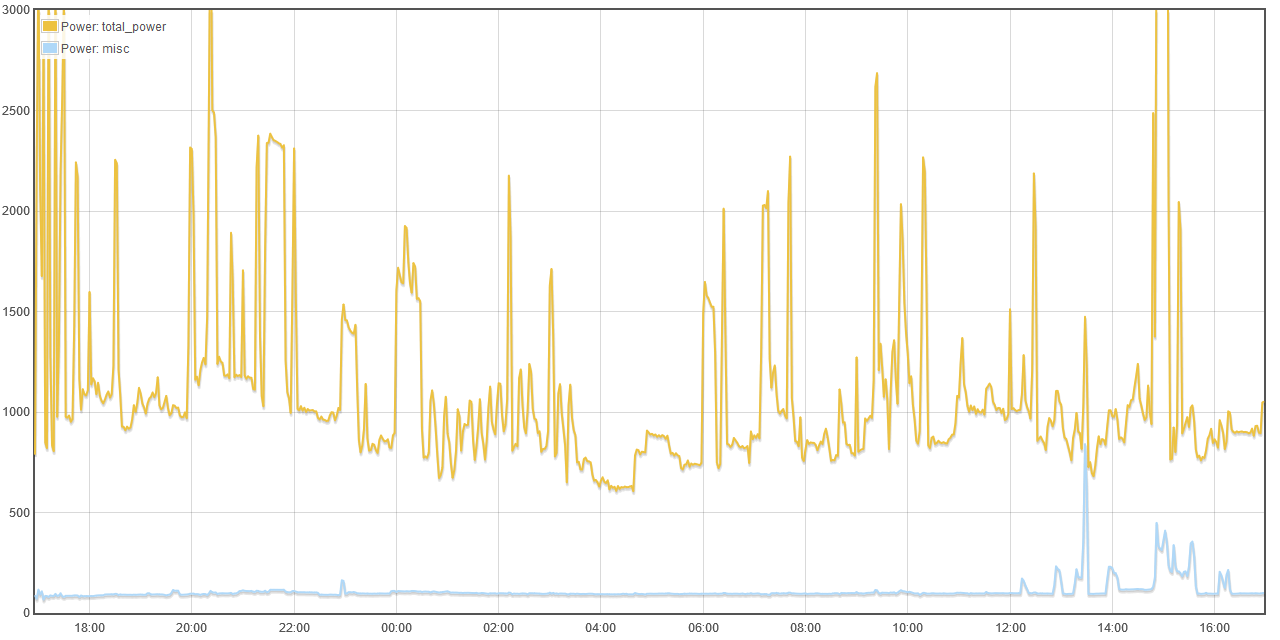
Some of these are multiple circuits, and the branch panel covers eight bed/bath/hall type circuits. What I do is subtract everything that is measured from the total to get a measure of what’s not directly measured.
You can see that the “misc” is pretty constant and amounts to about 90Watts continuously. I have identified these loads which are pretty much 24/7 things like a radon fan. The variation in the afternoon is activity in the garage. So I could measure these things directly, but they amount to a constant known load and are about 8% of my total use. If you catch the big fish - EV, AC, solar, etc. you will have a pretty good picture and be able to know the size of the ones that got away.
Just bundle your loads for that phase and put the splitcore ct around the bundle. All your a phase in a bundle wirh ct 1 and then all your b phase wires bundled for ct2 .